XE1205SKC868XE1 Semtech, XE1205SKC868XE1 Datasheet - Page 11
XE1205SKC868XE1
Manufacturer Part Number
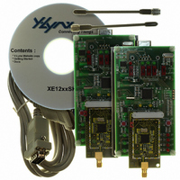
XE1205SKC868XE1
Description
KIT STARTER FOR XE1205 868MHZ
Manufacturer
Semtech
Series
TrueRF™r
Type
Transceiver, ISMr
Specifications of XE1205SKC868XE1
Frequency
868MHz
For Use With/related Products
XE1205 (868MHz)
Lead Free Status / RoHS Status
Contains lead / RoHS non-compliant


where OSR(7:0) is the content of the register; TParam_OSR(7:0) as described in section 7.2.8.
For a correct operation of the bit synchronizer, the value of this register must be higher or equal to 15 and
(int(OSR)+1) * Bit_rate should be inferior or equal to 4.87MHz.
5.2.3.3
In receive mode this feature is activated by setting the RXParam_Pattern configuration register bit to high. The
demodulated signal is compared with a pattern stored in the Reg_pattern(31:0) registers. The PATTERN signal (mapped
to output pin IRQ_0) is driven by the output of this comparator and is synchronized by DCLK. It is set to high when a
matching condition is detected, otherwise set to low. PATTERN output is updated at the rising edge of DCLK. The
number of bits used for comparison is defined in the RXParam_Psize(1:0) register and the number of tolerated errors for
the pattern recognition is defined in the RXParam_Ptol(1:0) register. Figure 4, illustrates the pattern matching process.
Note: The pattern recognizer is available only if the bit synchronizer is enabled.
5.2.3.4
This function provides a Received Signal Strength Indication based on the signal level at the output of the base-band
filter. To activate this function, the bit RXParam_RSSI must be set to “1”. When activated, the 2-bit status information is
stored in register RXParam_RSSI_OUT(1:0) and may be read through the serial control interface. The meaning of this
status information is given in the table below, where V
when the receiver is operated in mode A. The thresholds VTHRi are at the output of the base-band filter divided by the
gain between the input of the receiver and this output. When operated in mode B, equivalent VTHRi thresholds are
shifted 15dBm higher.
The operating range of the RSSI measurement may be changed by programming the RXParam_RSSI_range bit; in this
way two ranges with three VTHRi values may be selected. An additional way to increase RSSI operating range is to
combine modes A and B thresholds. One could then cover input signals ranging from -110dBm (VTHR1, low range,
mode A) up to -70dBm (VTHR3, high range, mode B)
© Semtech 2008
DCLK
DATA
(NRZ)
PATTERN
Pattern recognition block in continuous mode
RSSI in continuous mode
Reg_pattern[x]
Bit N-x =
RXPARAM_RSSI_out(1:0)
0 0
0 1
1 0
1 1
Reg_pattern[1]
Figure 4: Pattern matching operation.
Table 7: RSSI status description
Bit N-1 =
RFFIL
Reg_pattern[0]
Description
V
VTHR1 < V
VTHR2 < V
VTHR3 < V
RFFIL
11
is the differential amplitude of the equivalent input RF signal
Bit N =
≤ VTHR1
RFFIL
RFFIL
RFFIL
≤ VTHR2
≤ VTHR3
XE1205
www.semtech.com
Related parts for XE1205SKC868XE1
Image
Part Number
Description
Manufacturer
Datasheet
Request
R

Part Number:
Description:
Low-power, High Link Budget Integrated Uhf Transceiver
Manufacturer:
Semtech Corporation
Datasheet:

Part Number:
Description:
EVALUATION BOARD
Manufacturer:
Semtech
Datasheet:
Part Number:
Description:
EVALUATION BOARD
Manufacturer:
Semtech
Datasheet:
Part Number:
Description:
VOLTAGE SUPPRESSOR, TRANSIENT SEMTECH
Manufacturer:
Semtech
Datasheet:
Part Number:
Description:
HIGH VOLTAGE CAPACITORS MONOLITHIC CERAMIC TYPE
Manufacturer:
Semtech Corporation
Datasheet:
Part Number:
Description:
EZ1084CM5.0 AMP POSITIVE VOLTAGE REGULATOR
Manufacturer:
Semtech Corporation
Datasheet:
Part Number:
Description:
3.0 AMP LOW DROPOUT POSITIVE VOLTAGE REGULATORS
Manufacturer:
Semtech Corporation
Datasheet:
Part Number:
Description:
Manufacturer:
Semtech Corporation
Datasheet:
Part Number:
Description:
RailClamp Low Capacitance TVS Diode Array
Manufacturer:
Semtech Corporation
Datasheet:
Part Number:
Description:
Manufacturer:
Semtech Corporation
Datasheet:
Part Number:
Description:
Manufacturer:
Semtech Corporation
Datasheet:
Part Number:
Description:
Manufacturer:
Semtech Corporation
Datasheet: