DR-TRC103-868-DK RFM, DR-TRC103-868-DK Datasheet - Page 3
DR-TRC103-868-DK
Manufacturer Part Number
DR-TRC103-868-DK
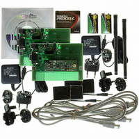
Description
RFIC TRANCEIVER DEVELOPMENT KIT
Manufacturer
RFM
Type
Transceiver, SRRr
Datasheets
1.DR-TRC103-868-DK.pdf
(1 pages)
2.DR-TRC103-868-DK.pdf
(22 pages)
3.DR-TRC103-868-DK.pdf
(6 pages)
Specifications of DR-TRC103-868-DK
Frequency
863MHz ~ 870MHz
For Use With/related Products
TRC103-868
Lead Free Status / RoHS Status
Lead free / RoHS Compliant
Other names
583-1056


TX/RX/SLP Mode Select Button
Power-up Configuration:
On power-up the board is initially configured to “Receive Continuous Mode”. See the
TRC103 Datasheet for a detailed explanation of Continuous Mode vs Buffered (Packet)
Mode. In this mode the Mode LED will be Green. Receive Continuous Mode allows the
user to connect a modulated signal from a signal generator source onto the board through
a short, coaxial cable and verify the demodulated signal with an oscilloscope through the
DAT pin.
Briefly pressing the “TX/RX/SLP Mode Select” button once configures the board into
“Transmit Continuous Mode”. The Mode LED will change color from Green to Yellow.
This mode turns on the transmitter. The frequency and output power may be verified on a
spectrum analyzer. A square-wave modulating signal may be applied to the DAT pin and
modulation observed on the spectrum analyzer.
Briefly pressing the “TX/RX/SLP Mode Select” button once again configures the board into
“Sleep Mode”. The Mode LED will turn off. Connecting an ammeter across the terminals
of J1, with the jumper removed, the user can verify the extremely low current usage of the
TRC103 device.
• Freq – 868.35 MHz
• Power - +10dBm
• ∆ƒ deviation – 50 kHz
• Data Rate – 2kbps
• RX Baseband BW – 100kHz
J1 – Ammeter Connection
Related parts for DR-TRC103-868-DK
Image
Part Number
Description
Manufacturer
Datasheet
Request
R

Part Number:
Description:
RFIC TRANCEIVER DEVELOPMENT KIT
Manufacturer:
RFM
Datasheet:

Part Number:
Description:
ASH RX 115.2 KBPS 433.92 MHZ
Manufacturer:
RFM
Datasheet:

Part Number:
Description:
RFIC TRANCEIVER MULTI-CHANNEL FS
Manufacturer:
RFM
Datasheet:

Part Number:
Description:
ASH TX 115.2 KBPS 433.92 MHZ
Manufacturer:
RFM
Datasheet:
Part Number:
Description:
Filters 1602MHz BW=61MHz
Manufacturer:
RFM
Datasheet:

Part Number:
Description:
RESONATOR, SM3030-6
Manufacturer:
RFM
Datasheet:

Part Number:
Description:
RESONATOR, SM3030-6
Manufacturer:
RFM
Datasheet:

Part Number:
Description:
RESONATOR, SM3030-6
Manufacturer:
RFM
Datasheet:

Part Number:
Description:
RESONATOR, SM5035-4
Manufacturer:
RFM
Datasheet:
Part Number:
Description:
RESONATOR 418MHZ SM5035-4
Manufacturer:
RFM
Datasheet:
Part Number:
Description:
WiFi / 802.11 Modules 2.4 and 5.8GHz + BT
Manufacturer:
RFM
Datasheet:

Part Number:
Description:
10-Terminal Ceramic Surface-Mount Case 7 x 5 mm Nominal Footprint
Manufacturer:
RFM [RF Monolithics, Inc]
Datasheet:
Part Number:
Description:
QUAD-BAND GSM850/GSM/DCS/PCS POWER AMP MODULE
Manufacturer:
RFM [RF Monolithics, Inc]
Datasheet:
Part Number:
Description:
402 to 405 MHz Medical Band Front-end Filter
Manufacturer:
RFM [RF Monolithics, Inc]
Datasheet: