WSN802GDK-A RFM, WSN802GDK-A Datasheet - Page 5
WSN802GDK-A
Manufacturer Part Number
WSN802GDK-A
Description
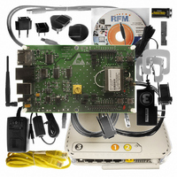
DEV KIT FOR WSN802G W/ROUTER
Manufacturer
RFM
Type
Transceiver, Wi-Fi / 802.11 b/gr
Specifications of WSN802GDK-A
Frequency
2.4GHz
Wireless Frequency
2.4 GHz
Interface Type
Ethernet, USB
Security
802.1x, WPA2
Operating Voltage
9 V
Antenna
Chip
For Use With/related Products
WSN802G
Lead Free Status / RoHS Status
Lead free / RoHS Compliant
Other names
583-1147


WSN802G Antenna Connector
A U.FL miniature coaxial connector is provided on both WSN802G configurations for connection to the RFIO port.
A short U.FL coaxial cable can be used to connect the RFIO port directly to an antenna. In this case the antenna
should be mounted firmly to avoid stressing the U.FL coaxial cable due to antenna mounting flexure. Alternately,
a U.FL coaxial jumper cable can be used to connect the WSN802G module to a U.FL connector on the host cir-
cuit board. The connection between the host circuit board U.FL connector and the antenna or antenna connector
on the host circuit board should be implemented as a 50 ohm stripline. Referring to Figure 3, the width of this
stripline depends on the thickness of the circuit board between the stripline and the groundplane. For FR-4 type
circuit board materials (dielectric constant of 4.7), the width of the stripline is equal to 1.75 times the thickness of
the circuit board. Note that other circuit board traces should be spaced away from the stripline to prevent signal
coupling, as shown in Figure 4. The stripline trace should be kept short to minimize its insertion loss.
www.RFM.com E-mail: info@rfm.com
©2009 by RF Monolithics, Inc.
Figure 3
Figure 2
Trace Separation from
50 ohm Microstrip
100 mil
150 mil
200 mil
250 mil
300 mil
Figure 4
Parallel to Microstrip
Length of Trace Run
125 mil
200 mil
290 mil
450 mil
650 mil
WSN802G - 04/29/09
Page 5 of 7
Related parts for WSN802GDK-A
Image
Part Number
Description
Manufacturer
Datasheet
Request
R

Part Number:
Description:
ASH RX 115.2 KBPS 433.92 MHZ
Manufacturer:
RFM
Datasheet:

Part Number:
Description:
RFIC TRANCEIVER MULTI-CHANNEL FS
Manufacturer:
RFM
Datasheet:

Part Number:
Description:
ASH TX 115.2 KBPS 433.92 MHZ
Manufacturer:
RFM
Datasheet:
Part Number:
Description:
Filters 1602MHz BW=61MHz
Manufacturer:
RFM
Datasheet:

Part Number:
Description:
RESONATOR, SM3030-6
Manufacturer:
RFM
Datasheet:

Part Number:
Description:
RESONATOR, SM3030-6
Manufacturer:
RFM
Datasheet:

Part Number:
Description:
RESONATOR, SM3030-6
Manufacturer:
RFM
Datasheet:

Part Number:
Description:
RESONATOR, SM5035-4
Manufacturer:
RFM
Datasheet:
Part Number:
Description:
RESONATOR 418MHZ SM5035-4
Manufacturer:
RFM
Datasheet:
Part Number:
Description:
RESONATOR 315 MHZ SMD
Manufacturer:
RFM
Datasheet:

Part Number:
Description:
Power Management Development Tools Wireless Temperature and Humidity Sensor
Manufacturer:
Powercast
Datasheet:

Part Number:
Description:
Power Management Development Tools Wireless Sensor Kit w/ WSG-101-SERIAL
Manufacturer:
Powercast
Datasheet:
Part Number:
Description:
Power Management Development Tools Wireless Sensor Kit w/ WSG-101-BACNET-IP
Manufacturer:
Powercast
Part Number:
Description:
10-Terminal Ceramic Surface-Mount Case 7 x 5 mm Nominal Footprint
Manufacturer:
RFM [RF Monolithics, Inc]
Datasheet: