SDK-AC4490-200A Laird Technologies, SDK-AC4490-200A Datasheet - Page 9
SDK-AC4490-200A
Manufacturer Part Number
SDK-AC4490-200A
Description
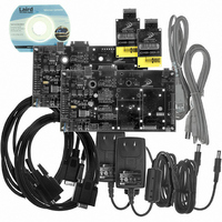
KIT DESIGN FOR AC4490-200A
Manufacturer
Laird Technologies
Series
AeroCommr
Type
Transceiverr
Specifications of SDK-AC4490-200A
Frequency
900MHz
Wireless Frequency
900 MHz
Interface Type
20-pin mini connector
Board Size
49 mm x 42 mm x 5 mm
Modulation
FHSS, FSK
Security
1 byte System ID, DES
Operating Voltage
3.3 VDC to 5.5 VDC
Output Power
200 mW
Antenna
MMCX
Operating Temperature Range
- 40 C to + 80 C
For Use With/related Products
AC4490-200A
Lead Free Status / RoHS Status
Contains lead / RoHS non-compliant
Lead Free Status / RoHS Status
Contains lead / RoHS non-compliant, Lead free / RoHS Compliant


RADIO VOLTAGE
(J9)
FORCED
CONFIGURATION
(J11)
POWER SOURCE
(J7)
Developer Kit User’s Manual
10/2/05
When this jumper is moved to the 40 Pin Header position, serial communication
is enabled through the 40 pin header (J3). Depending on the transceiver used,
signal levels will need to be either 3.3V or 5V.
When this jumper is moved to the USB Enable position, USB communication is
enabled through the USB Type B connector (J8).
When this jumper is moved to the +5V Radio position, the transceiver is
powered with 5V.
When this jumper is moved to the +3.3V Radio position, the transceiver is
powered with 3.3V. The AC4x90-1000, AC4868 and AC4x90-1x1 must have
this jumper set to 3.3V.
Special care should be taken when setting this jumper. An improper
setting can cause catastrophic damage to the transceiver.
When this jumper is moved to the Normal Operation position, the transceiver
will communicate at the Baud Rate configured in the EEPROM.
When the jumper is moved to the Forced 9600 Recovery position, the
transceiver interface baud rate is forced to 9600 Baud upon reset. This is for
EEPROM recovery only and should not be used in normal operation.
When this jumper is moved to the Power Conn position, power is supplied to
the SDK board through the power connector (J4).
When this jumper is moved to the Batteries position, power is supplied to the
SDK board through the two AA battery sockets on the bottom of the SDK board.
Special care should be taken when selecting batteries to power the SDK. High
quality Alkaline batteries should be used. Do not mix battery types or batteries
that have been used unequally as performance could suffer. Four Alkaline
batteries will produce a voltage of 6V. A minimum of 5.5V is required to power
the SDK board. Power should be constantly monitored when using battery
power.
If USB Power is selected, the transceiver and development board will receive
power from the USB port. USB power should only be used for AC4486,
AC4490, AC4790 and AC4868 product families. Most USB ports can only
supply 500mA of power max therefore it is recommended that USB power
only be used with transceivers that draw less than 300mA peak. Though
PCs should have over-current protection for their USB ports, drawing too
much current through the USB port has the potential to cause damage to
the PC and should be avoided.
9
Related parts for SDK-AC4490-200A
Image
Part Number
Description
Manufacturer
Datasheet
Request
R

Part Number:
Description:
KIT DESIGN FOR AC4868-250M
Manufacturer:
Laird Technologies
Datasheet:

Part Number:
Description:
KIT DESIGN FOR AC4486-5A
Manufacturer:
Laird Technologies
Datasheet:

Part Number:
Description:
KIT DESIGN FOR AC4486-5M
Manufacturer:
Laird Technologies
Datasheet:

Part Number:
Description:
KIT DEVELOPMENT FOR LT2510 U.FL
Manufacturer:
Laird Technologies
Datasheet:

Part Number:
Description:
KIT DEVELOPMENT FOR LT2510 ANT
Manufacturer:
Laird Technologies
Datasheet:

Part Number:
Description:
Bluetooth Serial Module Development Kit
Manufacturer:
Laird Technologies
Part Number:
Description:
BLUETOOTH MODULE DEVELOPMENT KIT
Manufacturer:
Laird Technologies
Part Number:
Description:
Bluetooth 2.0 AT Data Module, Internal Antenna Development Kit
Manufacturer:
Laird Technologies

Part Number:
Description:
BLUETOOTH EVAL BOARD BTM511
Manufacturer:
Laird Technologies
Datasheet:

Part Number:
Description:
Bluetooth / 802.15.1 Modules & Development Tools BLUETTH Multimed MODLE, No ANT DEVKIT
Manufacturer:
Laird Technologies
Datasheet:

Part Number:
Description:
CHOKE COMMON MODE 110 OHMS SMD
Manufacturer:
Laird Technologies
Datasheet: