RF5110GPCK-410 RFMD, RF5110GPCK-410 Datasheet - Page 17
RF5110GPCK-410
Manufacturer Part Number
RF5110GPCK-410
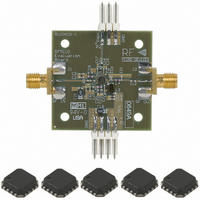
Description
KIT EVAL FOR RF5110G
Manufacturer
RFMD
Type
Amplifierr
Datasheet
1.RF5110GTR7.pdf
(22 pages)
Specifications of RF5110GPCK-410
Frequency
800MHz ~ 950MHz
For Use With/related Products
RF5110G
Lead Free Status / RoHS Status
Lead free / RoHS Compliant
Other names
689-1054
RF5110GPCBA-410
RF5110GPCBA-410
Available stocks
Company
Part Number
Manufacturer
Quantity
Price
Company:

Part Number:
RF5110GPCK-410
Manufacturer:
RFMD
Quantity:
5 000


PCB Surface Finish
The PCB surface finish used for RFMD’s qualification process is electroless nickel, immersion gold. Typical thickness is 3μinch
to 8μinch gold over 180μinch nickel.
PCB Land Pattern Recommendation
PCB land patterns are based on IPC-SM-782 standards when possible. The pad pattern shown has been developed and tested
for optimized assembly at RFMD; however, it may require some modifications to address company specific assembly pro-
cesses. The PCB land pattern has been developed to accommodate lead and package tolerances.
PCB Metal Land Pattern
Figure 1. PCB Metal Land Pattern (Top View)
Rev A4 DS071026
7628 Thorndike Road, Greensboro, NC 27409-9421 · For sales or technical
support, contact RFMD at (+1) 336-678-5570 or sales-support@rfmd.com.
0.55 Typ.
0.50 Typ.
0.55 Typ.
PCB Design Requirements
Pin 1
0.50 Typ.
Pin 16
A
A
A
A
A = 0.64 x 0.28 (mm) Typ.
B = 0.28 x 0.64 (mm) Typ.
C = 1.50 (mm) Sq.
B
B
1.50 Typ.
B
B
C
0.75 Typ.
B
B
B
B
Pin 8
Dimensions in
mm.
A
A
A
A
Pin 12
0.75 Typ.
1.50
Typ.
RF5110G
17 of 22
Related parts for RF5110GPCK-410
Image
Part Number
Description
Manufacturer
Datasheet
Request
R

Part Number:
Description:
3V GSM POWER AMPLIFIER
Manufacturer:
RF Micro Devices
Datasheet:

Part Number:
Description:
IC AMP HBT GAAS CATV 8-SOIC
Manufacturer:
RFMD
Datasheet:

Part Number:
Description:
IC AMP MMIC GAAS 12GHZ 4-MICROX
Manufacturer:
RFMD
Datasheet:

Part Number:
Description:
IC AMP 3V LOW-NOISE SOT23-6
Manufacturer:
RFMD
Datasheet:

Part Number:
Description:
KIT EVAL FOR NBB-310
Manufacturer:
RFMD
Datasheet:
Part Number:
Description:
IC AMPLIFIER MMIC LNA 8-QFN
Manufacturer:
RFMD
Datasheet:
Part Number:
Description:
IC AMP MMIC GAAS 4GHZ 4-MICROX
Manufacturer:
RFMD
Datasheet:
Part Number:
Description:
IC SWITCH 10W PHEMT SPDT 12QFN
Manufacturer:
RFMD
Datasheet:
Part Number:
Description:
IC QUADRATURE MODULATOR 16-SOIC
Manufacturer:
RFMD
Datasheet:
Part Number:
Description:
100MHZ TO 4000MHZ, GAAS PHEMT MMIC LOW NOISE AMPLIFIERS
Manufacturer:
RFMD
Part Number:
Description:
KIT EVAL FOR RF2336
Manufacturer:
RFMD
Datasheet:


Part Number:
Description:
IC AMP WLAN/LNA DVR 3V SOT23-5
Manufacturer:
RFMD
Datasheet:

Part Number:
Description:
IC AMP HBT GAAS LNA BYPASS 8-QFN
Manufacturer:
RFMD
Datasheet: