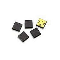
ACMD-7612-TR1 Avago Technologies US Inc., ACMD-7612-TR1 Datasheet - Page 8

ACMD-7612-TR1
Manufacturer Part Number
ACMD-7612-TR1
Description
DUPLEXER FBAR MINI UMTS 2.5X3MM
Manufacturer
Avago Technologies US Inc.
Series
-r
Datasheet
1.ACMD-7612-TR1.pdf
(12 pages)
Specifications of ACMD-7612-TR1
Frequency Bands (low / High)
1.92GHz ~ 1.98GHz / 2.11GHz ~ 2.17GHz
Low Band Attenuation (min / Max Db)
53.00dB / -
High Band Attenuation (min / Max Db)
41.00dB / -
Return Loss (low Band / High Band)
20dB / 16dB
Mounting Type
Surface Mount
Package / Case
3-CSP
Function
Designed for UMTS Band I handsets
Lead Free Status / RoHS Status
Contains lead / RoHS non-compliant
Lead Free Status / RoHS Status
Lead free / RoHS Compliant, Contains lead / RoHS non-compliant
Available stocks
Company
Part Number
Manufacturer
Quantity
Price
Company:
Part Number:
ACMD-7612-TR1
Manufacturer:
AVAGO
Quantity:
311
Ø 0.20 VIA ARRAY
HORIZ PITCH = 0.33
VERT PITCH = 0.38
Figure 20. PCB layout
A PCB layout implementing design principles similar to
those illustrated in Figure 16 is recommended to optimize
performance of the ACMD-7612.
It is particularly important to maximize isolation between
the Tx connection to the duplexer and the Rx port. High
isolation is achieved by (1) maintaining a continuous
ground plane around the duplexer mounting area,
(2) surrounding the I/O ports with sufficient ground
vias to enclose the connections in a “Faraday cage”, and
(3) preferably routing the Tx trace in a different metal
layer than the Rx.
The latter is especially useful, not only to maintain Tx-
Rx isolation of the duplexer, but also to prevent leakage
of the Tx signal into other components that could
result in the creation of intermodulation products and
degradation of overall system performance.
8
W
0.10
G
Tx
Notes:
1. Dimensions in mm.
2. Transmission line Gap (G) and Width (W) adjusted for Zo = 50 ohms.
3. I/O Pads (3 ea) 0.53 x 0.53, corner chamfer 0.30.
4. I/O Pad to Ground plane gap = 0.34, corner chamfer 0.30.
5. Ground vias positioned to maximize port-to-port isolation.
0.10
2.27
Ant
Figure 21. ACMD-7612 superposed on PCB layout
R x
Ø 0.20 VIA ARRAY
HORIZ PITCH = 0.33
VERT PITCH = 0.38
Ø 0.20 VIA ARRAY
HORIZ PITCH = 0.38
VERT PITCH = 0.33
Ø 0.20 VIA ARRAY
HORIZ PITCH = 0.38
1.78


