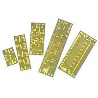
AMMC-3040-W10 Avago Technologies US Inc., AMMC-3040-W10 Datasheet - Page 5

AMMC-3040-W10
Manufacturer Part Number
AMMC-3040-W10
Description
IC MMIC MIXER W/LO AMP&MULT GAAS
Manufacturer
Avago Technologies US Inc.
Series
AMMC-3040r
Datasheet
1.AMMC-3040-W50.pdf
(6 pages)
Specifications of AMMC-3040-W10
Function
Mixer
Supply Current
50mA
Supply Voltage Range
2V To 5V
Frequency Max
36GHz
Frequency Min
18GHz
Supply Voltage Max
5V
Supply Voltage Min
2V
Lead Free Status / RoHS Status
Lead free / RoHS Compliant
Lead Free Status / RoHS Status
Lead free / RoHS Compliant, Lead free / RoHS Compliant
Available stocks
Company
Part Number
Manufacturer
Quantity
Price
Part Number:
AMMC-3040-W10
Manufacturer:
AVAGO/安华高
Quantity:
20 000
Figure 15. AMMC-3040 Bond pad locations, dimensions in microns
Figure 16. AMMC-3040 assembly diagram
(Note: To assure stable operation bias supply feeds should be bypassed to ground with a capacitor, Cb ≥ 100 pF typical.)
Biasing for Fundamental Mixing
The recommended DC bias condition for the AMMC-
3040 LO amplifier when used as a fundamental frequen-
cy mixer is with all four drains connected to a single 3.5
to 4.5 V supply and all four gates connected to an adjust-
able negative supply voltage as shown in Figure 16(a).
The gate voltage is adjusted for a total drain supply cur-
rent of typically 150 to 250 mA.
The second, third, and fourth stage DC drain bias lines
are connected internally and therefore require only a
single bond wire. A separate bond wire is needed for the
first stage DC drain bias, V
5
480
96
Gold Plated Shim
(optional)
760
0
(a) Fundamental LO. Single drain and single gate supply assembly
for using the LO amplifier in fundamental frequency mixer applications.
LO
LO
To V
Supply Feed
Cb
0
0 98
DD
82
DC Drain
V g1
To V
Supply Feed
GG
Cb
DC Gate
420
V d1
100 pF
d1
568
.
V g2
100 pF
700
V g2
894
914
V g3
V d2
IF
0.6 pF
~500 µm long
wire
To V
Supply Feed
1141
V d3
GG
RF
DC Gate
1320
V g4
Gold Plated Shim
(optional)
1475
The third and fourth stage DC gate bias lines are con-
nected internally. A total of three DC gate bond wires are
required: one for V
connection. The internal matching circuitry at the RF in-
put creates a 50-ohm DC and RF path to ground. Any
DC voltage applied to the RF input must be maintained
below 1 volt, otherwise, a blocking capacitor should be
used. The RF output is AC coupled.
No ground bond wires are needed since the ground con-
nection is made by means of plated through via holes to
the backside of the chip.
V d4
(b) Sub-harmonic LO. Separate first-stage gate bias supply to use
the LO amplifier as a multiplier for application as a sub-harmonic mixer.
LO
To V
100 pF
Supply Feed
Cb
DD
DC Drain
2018
2018
Cb
IF
g1
IF
, one for V
100 pF
Cb
100 pF
g2
, and one for the V
1720
2520
To V
Supply Feed
RF
GG
IF
0.6 pF
DC Gate
760
300
~500 µm long
wire
RF
g3
/V
g4


