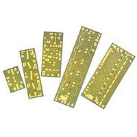
AMMC-6140-W50 Avago Technologies US Inc., AMMC-6140-W50 Datasheet - Page 3

AMMC-6140-W50
Manufacturer Part Number
AMMC-6140-W50
Description
IC MMIC FREQ MULT DUAL 20-40GHZ
Manufacturer
Avago Technologies US Inc.
Datasheet
1.AMMC-6140-W50.pdf
(6 pages)
Specifications of AMMC-6140-W50
Function
Frequency Multiplier
Supply Current
27mA
Supply Voltage Range
4.5V
Frequency Max
20GHz
Frequency Min
10GHz
Supply Voltage Max
7V
Gain
1dB
Lead Free Status / RoHS Status
Lead free / RoHS Compliant
Lead Free Status / RoHS Status
Lead free / RoHS Compliant, Lead free / RoHS Compliant
Available stocks
Company
Part Number
Manufacturer
Quantity
Price
Part Number:
AMMC-6140-W50
Manufacturer:
AVAGO/安华高
Quantity:
20 000
AMMC-6140 Typical Performances (T
NOTE: These measurements are in a 50Ω test environment. Aspects of the multiplier performance may be improved
over a narrower bandwidth by application of additional conjugate, linearity, or low noise (Γopt) matching.
3
Figure 1. Typical Output Power against
Fundamental, 3
(P
Figure 7. Typical Output Power and
Fundamental Suppression vs. Temperature.
Figure 4. Typical Output Power against
Fundamental 3
suppression vs. P
-10
-15
-20
-25
-30
-35
-40
-45
-10
-15
-20
-25
-30
-35
-40
-15
-25
-35
-45
-55
-5
-5
-5
in
5
0
5
0
5
-11
16
16
=3 dBm) vs. Frequency.
-9
20
20
OUTPUT FREQUENCY (GHz)
OUTPUT FREQUENCY (GHz)
-7
24
24
rd
rd
, and 4
and 4
in
-5
O/P Freq=2*Fin
Fundamental
3H
4H
2H (@-40°C)
2H (@+25°C
2H (@+85°C
1H (@-40°C)
1H (@+25°C
1H (@+85°C)
Pin (dBm)
(2H=22 GHz).
28
28
th
-3
th
Harmonic
32
Harmonic suppression
32
-1
36
36
1
2H=22 GHz
3H
4H
Fin
40
40
A
3
= 25°C, V
44
44
5
d
Figure 5. Typical Output Power against
Fundamental and 3
(2H=30 GHz).
Figure 2. Typical Output Power at different
Fundamental Input Power vs. Frequency.
Figure 8. Typical Output Power and
Fundamental Suppression vs. Vdd.
=4 .5V, I
-15
-25
-35
-45
-55
-10
-15
-20
-25
-30
-35
-40
-10
-5
-5
-2
-4
-6
-8
2
0
5
5
0
-11
16
16
-9
20
20
D
OUTPUT FREQUENCY (GHz)
OUTPUT FREQUENCY (GHz)
= 27 mA, Vg = -1.2V, Z
-7
24
24
-5
Pin (dBm)
2H (@4.0V)
2H (@4.5V)
2H (@5.0V)
1H (@4.0V)
1H (@4.5V)
1H (@5.0V)
rd
28
28
Harmonic vs. P
2H=30 GHz
3H
Fin
-3
32
32
-1
Pin=-2 dBm
Pin=0 dBm
Pin=+2 dBm
Pin=+4 dBm
Pin=+5 dBm
36
36
1
in
40
40
3
in
44
44
5
= Z
out
= 50Ω unless otherwise stated)
Figure 3. Typical Input & Output Return Loss.
Figure 6. Typical Output Power against
Fundamental vs. P
Figure 9. Typical Pout and Fundamental
Suppression vs. Vg (Fout=38 GHz).
-10
-15
-20
-25
-30
-15
-25
-35
-45
-55
-10
-20
-30
-40
-50
10
-5
-5
0
5
0
-11
-11
4
-9
-9
12
-7
-7
FREQUENCY (GHz)
-5
-5
in
Pin (dBm)
Pin (dBm)
20
(2H=38 GHz).
-3
-3
2H (@Vg=-1.0)
2H (@Vg=-1.2)
2H (@Vg=-1.4)
1H (@Vg=-1.0)
1H (@Vg=-1.2)
1H (@Vg=-1.4)
28
-1
-1
2H=38 GHz
Fin
1
1
36
S11
S22
3
3
44
5
5


