LMH2100TM/NOPB National Semiconductor, LMH2100TM/NOPB Datasheet - Page 29
LMH2100TM/NOPB
Manufacturer Part Number
LMH2100TM/NOPB
Description
IC LOG DETECTOR 4GHZ 40DB 6MSMD
Manufacturer
National Semiconductor
Datasheet
1.LMH2100TMNOPB.pdf
(32 pages)
Specifications of LMH2100TM/NOPB
Frequency
50MHz ~ 4GHz
Rf Type
Cellular, W-CDMA, CDMA, GSM, UMTS
Input Range
-45dBm ~ -5dBm
Accuracy
0.5dB
Voltage - Supply
2.7 V ~ 3.3 V
Current - Supply
9.2mA
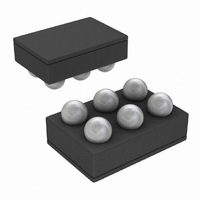
Package / Case
6-UFBGA
Pin Count
6
Screening Level
Industrial
Lead Free Status / RoHS Status
Lead free / RoHS Compliant
Other names
LMH2100TMTR


Low frequency supply voltage variations due to PA switching
might result in a ripple at the output voltage. The LMH2100
has a Power Supply Rejection Ration of 60 dB for low fre-
quencies.
4.1.2 Ground (GND)
The LMH2100 needs a ground plane free of noise and other
disturbing signals. It is important to separate the RF ground
return path from the other grounds. This is due to the fact that
the RF input handles large voltage swings. A power level of
0 dBm will cause a voltage swing larger than 0.6 V
internal 50Ω input resistor. This will result in a significant RF
return current toward the source. It is therefore recommended
that the RF ground return path not be used for other circuits
in the design. The RF path should be routed directly back to
the source without loops.
4.2 RF Input Interface
The LMH2100 is designed to be used in RF applications,
having a characteristic impedance of 50Ω. To achieve this
impedance, the input of the LMH2100 needs to be connected
via a 50Ω transmission line. Transmission lines can be easily
created on PCBs using microstrip or (grounded) coplanar
waveguide (GCPW) configurations. This section will discuss
both configurations in a general way. For more details about
designing microstrip or GCPW transmission lines, a mi-
crowave designer handbook is recommended.
4.2.1 Microstrip Configuration
One way to create a transmission line is to use a microstrip
configuration. A cross section of the configuration is shown in
Figure 15, assuming a two layer PCB.
FIGURE 14. Recommended Board Layout
PP
, over the
29
A conductor (trace) is placed on the topside of a PCB. The
bottom side of the PCB has a fully copper ground plane. The
characteristic impedance of the microstrip transmission line
is a function of the width W, height H, and the dielectric con-
stant ε
Characteristics such as height and the dielectric constant of
the board have significant impact on transmission line dimen-
sions. A 50Ω transmission line may result in impractically wide
traces. A typical 1.6 mm thick FR4 board results in a trace
width of 2.9 mm, for instance. This is impractical for the
LMH2100, since the pad width of the 6-Bump micro SMD
package is 0.24 mm. The transmission line has to be tapered
from 2.9 mm to 0.24 mm. Significant reflections and reso-
nances in the frequency transfer function of the board may
occur due to this tapering.
4.2.2 GCPW Configuration
A transmission line in a (grounded) coplanar waveguide
(GCPW) configuration will give more flexibility in terms of
trace width. The GCPW configuration is constructed with a
conductor surrounded by ground at a certain distance, S, on
the top side. Figure 16 shows a cross section of this configu-
ration. The bottom side of the PCB is a ground plane. The
ground planes on both sides of the PCB should be firmly con-
r
.
FIGURE 15. Microstrip Configuration
30014090
30014080
www.national.com
Related parts for LMH2100TM/NOPB
Image
Part Number
Description
Manufacturer
Datasheet
Request
R

Part Number:
Description:
50 MHz to 4 GHz 40 dB Logarithmic Power Detector for CDMA and Wcdma
Manufacturer:
National Semiconductor Corporation
Datasheet:

Part Number:
Description:
National Semiconductor [8-Bit D/A Converter]
Manufacturer:
National Semiconductor
Datasheet:
Part Number:
Description:
National Semiconductor [Media Coprocessor]
Manufacturer:
National Semiconductor
Datasheet:
Part Number:
Description:
Digitally Controlled Tone and Volume Circuit with Stereo Audio Power Amplifier, Microphone Preamp Stage and National 3D Sound
Manufacturer:
National Semiconductor
Datasheet:
Part Number:
Description:
Digitally Controlled Tone and Volume Circuit with Stereo Audio Power Amplifier, Microphone Preamp Stage and National 3D Sound
Manufacturer:
National Semiconductor
Datasheet:
Part Number:
Description:
AC97 Rev 2 Codec with Sample Rate Conversion and National 3D Sound
Manufacturer:
National Semiconductor
Part Number:
Description:
Manufacturer:
National Semiconductor
Datasheet:
Part Number:
Description:
Manufacturer:
National Semiconductor
Datasheet:
Part Number:
Description:
General Purpose, Low Voltage, Low Power, Rail-to-Rail Output Operational Amplifiers
Manufacturer:
National Semiconductor
Datasheet:
Part Number:
Description:
8-bit 20 MSPS flash A/D converter.
Manufacturer:
National Semiconductor
Datasheet:
Part Number:
Description:
Low Noise Quad Operational Amplifier
Manufacturer:
National Semiconductor
Datasheet:
Part Number:
Description:
Quad Differential Line Receivers
Manufacturer:
National Semiconductor
Datasheet:
Part Number:
Description:
Quad High Speed Trapezoidal? Bus Transceiver
Manufacturer:
National Semiconductor
Datasheet:
Part Number:
Description:
Dual Line Receiver
Manufacturer:
National Semiconductor
Datasheet: