4313-114-00158 Yageo, 4313-114-00158 Datasheet - Page 6
4313-114-00158
Manufacturer Part Number
4313-114-00158
Description
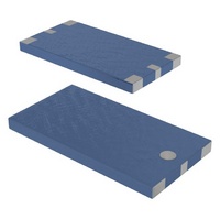
ANTENNA GPS LP-MODE CERAMIC SMD
Manufacturer
Yageo
Datasheet
1.4313-114-00158.pdf
(8 pages)
Specifications of 4313-114-00158
Antenna Type
Chip
Number Of Bands
1
Frequency
1.575GHz (1.525Mhz ~ 1.625Mhz)
Vswr
2
Gain
1.5dBi
Termination
Surface Mount
Mounting Type
Surface Mount
Height (max)
0.04" (1.1mm)
Lead Free Status / RoHS Status
Lead free / RoHS Compliant
Other names
311-1225
311-1225-1
311-1225-1
311-1225-2
311-1225-2
4311-114-00158
431111400158
431311400158
CAN4313114001581B
311-1225-1
311-1225-1
311-1225-2
311-1225-2
4311-114-00158
431111400158
431311400158
CAN4313114001581B


RELIABILITY DATA (Reference to IEC Specification)
4.4
4.5
4.6.1
4.8
4.9
4.10
R&D
Cliff Wang, Ph.D.
spec.doc
CECC 32
CLAUSE
384-10/
IEC
100
METHOD
6006868-2
TEST
IEC
Tb
Multilayer Ceramic Antenna
(LP Mode) for GPS (1.575GHz)
Print date 01/12/13
PHYCOMP
Mounting
Visual inspection
and dimension
check
Antenna
Adhesion
Bond strength of
plating on end face
Resistance to
soldering heat
TEST
2001-3-29
The antenna can be
mounted on printed-
circuit boards or ceramic
substrates by applying
wave soldering, reflow
soldering (including
vapour phase soldering)
or conductive adhesive
Any applicable method
using 10
magnification
Frequency = 1.575 GHz;
at 20 o C
A force of 5 N applied
for 10 s to the line
joining the terminations
and in a plane parallel to
the substrate
Mounted in accordance
with CECC 32 100,
paragraph 4.4
Conditions: bending
1mm at a rate of 1mm/s,
radius jig. 340 mm,
1 mm warp on FR4
board of 90 mm length
260
in a static solder bath
PROCEDURE
5 C for 10 0.5 s
Page
4313 114 00158
6
sheet 190-6
Preliminary use only
No visible damage
In accordance with
specification (no chip
off 3 mm)
Standard test board
in page 4
No visible damage
No visible damage
No visible damage
The terminations
shall be well tinned
after recovery and
Central Freq. Change
REQUIREMENTS
6%
2001-3-29
A4
Related parts for 4313-114-00158
Image
Part Number
Description
Manufacturer
Datasheet
Request
R

Part Number:
Description:
STDF 4313 NYL HEX
Manufacturer:
ABBATRON HH SMITH
Datasheet:

Part Number:
Description:
ANTENNA EGSM/DCS DUAL BAND SMD
Manufacturer:
Yageo
Datasheet:

Part Number:
Description:
ANTENNA CERM LP-MODE 433MHZ SMD
Manufacturer:
Yageo
Datasheet:
Part Number:
Description:
ANTENNA 802.11A DIELCTRC RES SMD
Manufacturer:
Yageo
Datasheet:

Part Number:
Description:
YAGEO 22pF ±5% 50V NPO
Manufacturer:
Yageo
Datasheet: