A6250 Antenova, A6250 Datasheet - Page 9
A6250
Manufacturer Part Number
A6250
Description
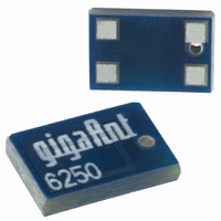
ANTENNA CHIP 2.4GHZ SMD RIGHT FD
Manufacturer
Antenova
Series
Impexar
Specifications of A6250
Antenna Type
Chip
Number Of Bands
1
Frequency
2.4GHz ~ 2.5GHz
Vswr
1.9
Gain
0dBi
Termination
Surface Mount
Mounting Type
Surface Mount
Height (max)
0.04" (1.25mm)
Technology Type
Internal SMD Chip Antenna
Termination Style
SMD/SMT
Dimensions
6.1 mm L x 3.9 mm W x 1.1 mm H
Mounting Style
SMD/SMT
Lead Free Status / RoHS Status
Lead free / RoHS Compliant
Other names
3030A6250-01
627-1014-2
627-1014-2
Available stocks
Company
Part Number
Manufacturer
Quantity
Price

Part Number:
A6250
Manufacturer:
AIT-IC
Quantity:
20 000
Company:
Part Number:
A62500116W
Manufacturer:
AD
Quantity:
6 226
Company:
Part Number:
A6250016W
Manufacturer:
CY
Quantity:
2 761
Part Number:
A6250E3R-15
Manufacturer:
AIT-IC
Quantity:
20 000
Part Number:
A6250E3R-18
Manufacturer:
AIT-IC
Quantity:
20 000
Part Number:
A6250E3R-25
Manufacturer:
AIT-IC
Quantity:
20 000
Part Number:
A6250E3R-28
Manufacturer:
AIT-IC
Quantity:
20 000
Company:
Part Number:
A6250E3R-33
Manufacturer:
MAXIM
Quantity:
1 000


14 Application example
The antenna is of a quarter wave type and is dependent on the groundplane area to complete the antenna
function. The antenna performance is also dependent on the size of the groundplane and the tranparent area.
1.
2.
3.
4.
5.
6.
7.
Placement of the antenna
The antenna shall be placed on a transparent area without underlying groundplane at the edge of the
PCB oriented as above. Groundplane area surrounding the antenna should be with a clearence of
G=3-5 mm
Placement of 2.4 GHz module
To avoid losses in the strip line, the module shall be placed as close to the antenna as possible.
Strip line
The strip line must be dimensioned according to your specific PCB. (see fig 1). No crossing strip lines
are allowed between the strip line and its ground plane.
Via Connections
To avoid spurious effects via connections must be made to analogue ground.
Component matching
Component values are depending on antenna placement, PCB dimensions and location of other
components.
DC Block
Might be needed depending on RF Module configuration.
Clearance
No components allowed within the clearence area with a minimum distance to other components,
C= 3-5 mm.
Note ! Incorrect implementation of the antenna will affect the performance.
Integrated Antenna Solutions
Contact Antenova for implementation services.
Front Surface
2.4 GHz
Radio
Impexa 2.4 GHz SMD Antenna
C
G
G
G
G
Back Surface
C
Product Specification AE040034-B
9
Related parts for A6250
Image
Part Number
Description
Manufacturer
Datasheet
Request
R

Part Number:
Description:
ANTENNA CHIP 2.4GHZ SMD
Manufacturer:
Antenova
Datasheet:

Part Number:
Description:
ANTENNA FUSCA 2.4GHZ SMD
Manufacturer:
Antenova
Datasheet:

Part Number:
Description:
ANTENNA CHIP 2.4GHZ SMD RIGHT FD
Manufacturer:
Antenova
Datasheet:

Part Number:
Description:
ANTENNA CHIP 2.4GHZ SMD LEFT FD
Manufacturer:
Antenova
Datasheet:

Part Number:
Description:
ANTENNA MIXTUS 2.4/5GHZ SMD
Manufacturer:
Antenova
Datasheet:

Part Number:
Description:
ANTENNA CHIP 2.4GHZ SMD
Manufacturer:
Antenova
Datasheet:

Part Number:
Description:
ANTENNA BREVIS GPS 1575MHZ SMD
Manufacturer:
Antenova
Datasheet:

Part Number:
Description:
ANTENNA CALVUS 824-960MHZ SMD
Manufacturer:
Antenova
Datasheet:

Part Number:
Description:
ANTENNA GPS 1575MHZ SMD
Manufacturer:
Antenova
Datasheet:

Part Number:
Description:
ANTENNA 2.4GHZ SNAP-IN 0.8MM PCB
Manufacturer:
Antenova
Datasheet:

Part Number:
Description:
ANTENNA 2.4GHZ W/SMA
Manufacturer:
Antenova
Datasheet:

Part Number:
Description:
ANTENNA CHIP 2.4GHZ SMD LEFT FD
Manufacturer:
Antenova
Datasheet:

Part Number:
Description:
ANTENNA REFLEXUS 824-960MHZ SMD
Manufacturer:
Antenova
Datasheet:
Part Number:
Description:
ANTENNA 2.4GHZ W/REV THREAD SMA
Manufacturer:
Antenova
Datasheet:
Part Number:
Description:
ANTENNA CHIP 2.4GHZ SMD
Manufacturer:
Antenova
Datasheet: