A10137 Antenova, A10137 Datasheet - Page 8
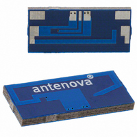
A10137
Manufacturer Part Number
A10137
Description
ANTENNA GPS 1575MHZ SMD
Manufacturer
Antenova
Series
GPSr
Specifications of A10137
Antenna Type
Chip
Number Of Bands
1
Frequency
1.575GHz (1.525Mhz ~ 1.625Mhz)
Vswr
1.5
Gain
-4.4dBi
Termination
Surface Mount
Mounting Type
Surface Mount
Height (max)
0.06" (1.6mm)
Technology Type
Internal GPS SMD Chip Antenna
Termination Style
SMD/SMT
Dimensions
20.1 mm L x 9 mm W x 1.6 mm H
Mounting Style
SMD/SMT
Lead Free Status / RoHS Status
Lead free / RoHS Compliant
Other names
627-1015-2
A10137-V1-1
A10137-V1-1


10 General Application Guidelines
11 Lead Free Soldering
The antenna has been tested and approved for lead free soldering. (See 12.4). Follow the guidelines and
reflow temperature vs time data for the solder paste supplied by the solder manufacturer.
12 Test Standards Conformance
(Information provided in this section is based on similarity and analysis with Antenova’s existing products.
Results from testing (in progress) will be released in future revisions of this product specification.)
12-1 Temperature
Antenna shall suffer no physical damage or performance degradation under the following operating conditions.
Item
Operating Temperature
Temperature Cycling
1.
2.
3.
4.
5.
6.
7.
Placement of the antenna.
The antenna shall be placed on an area with the PCB cut out (see drawing on page 7), preferably at the
edge of the PCB.
Placement of GPS radio module.
To avoid losses in the strip line, the module shall be placed as close to the antenna as possible.
Matching Circuit
The antenna requires a matching circuit, a PI network is recommended. This should be placed as close
to the antenna feed as possible.
Component values are depending on antenna placement, PCB dimensions and location of other
components.
Vias should connect all ground layers. Vias should be used to fence in the feed track from the radio to
the antenna. Vias should also be placed close to the ground pads of matching components. Vias size
and spacing depends on the application but generally 0.3 to 0.5mm diameter, spacing 3 to 10mm.
Strip line.
The strip line must be dimensioned according to your specific PCB. No crossing strip lines are allowed
between the strip line and its ground plane.
Via connections.
To avoid spurious effects, via connections must be made to analogue ground.
Clearance.
Minimum clearance to other components is 2-5 mm.
Casing material.
No metal casing or plastics using metal flakes shall be used, avoid also metallic based paint or laquer.
Note ! Incorrect implementation of the antenna will affect the performance.
Contact Antenova for implementation services and technical support.
Integrated Antenna Solutions
Standard
EN/IEC 60068-2-2
Test: Bd Dry Heat
EN/IEC 60068-2-14
Test: Na Change of Temperature
GPS RADIONOVA
Part No. A10137
Requirement
-30degC to +90degC
-40degC to +90degC
®
Co-planar Antenna
Procedure
500 cycles/10 min
Product Specification 06MD-0001-2-PS
8
Related parts for A10137
Image
Part Number
Description
Manufacturer
Datasheet
Request
R

Part Number:
Description:
ANTENNA CHIP 2.4GHZ SMD
Manufacturer:
Antenova
Datasheet:

Part Number:
Description:
ANTENNA FUSCA 2.4GHZ SMD
Manufacturer:
Antenova
Datasheet:

Part Number:
Description:
ANTENNA CHIP 2.4GHZ SMD RIGHT FD
Manufacturer:
Antenova
Datasheet:

Part Number:
Description:
ANTENNA CHIP 2.4GHZ SMD LEFT FD
Manufacturer:
Antenova
Datasheet:

Part Number:
Description:
ANTENNA MIXTUS 2.4/5GHZ SMD
Manufacturer:
Antenova
Datasheet:

Part Number:
Description:
ANTENNA CHIP 2.4GHZ SMD
Manufacturer:
Antenova
Datasheet:

Part Number:
Description:
ANTENNA BREVIS GPS 1575MHZ SMD
Manufacturer:
Antenova
Datasheet:

Part Number:
Description:
ANTENNA CALVUS 824-960MHZ SMD
Manufacturer:
Antenova
Datasheet:

Part Number:
Description:
ANTENNA 2.4GHZ SNAP-IN 0.8MM PCB
Manufacturer:
Antenova
Datasheet:

Part Number:
Description:
ANTENNA 2.4GHZ W/SMA
Manufacturer:
Antenova
Datasheet:

Part Number:
Description:
ANTENNA CHIP 2.4GHZ SMD LEFT FD
Manufacturer:
Antenova
Datasheet:

Part Number:
Description:
ANTENNA CHIP 2.4GHZ SMD RIGHT FD
Manufacturer:
Antenova
Datasheet:
Part Number:
Description:
ANTENNA CHIP 2.4GHZ SMD
Manufacturer:
Antenova
Datasheet:

Part Number:
Description:
GENERAL PURPOSE & SPECIALTY HOLE SAWS, BOXED ARBORS - With High Speed Steel Pilot Drill., Arbor W/HS Pilot Drill, For 3/8" Chuck, Saws 1-1/4"-6"
Manufacturer:
STARRETT

Part Number:
Description:
Programming Socket Adapters & Emulators 10 PIN TO 20 PIN JTAG ADAPTER
Manufacturer:
Code Red Technologies
Datasheet: