WS2512-TR1 Avago Technologies US Inc., WS2512-TR1 Datasheet - Page 19
WS2512-TR1
Manufacturer Part Number
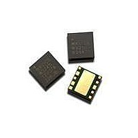
WS2512-TR1
Description
MODULE PA UMTS2100 4X4MM 10-PIN
Manufacturer
Avago Technologies US Inc.
Type
Power Amplifierr
Specifications of WS2512-TR1
Package / Case
10-DFN
Current - Supply
465mA ~ 510mA
Frequency
1.92GHz ~ 1.98GHz
Gain
23.5dB ~ 26.5dB
Rf Type
W-CDMA, HSPDA
Voltage - Supply
3.2V ~ 4.2V
Operating Frequency
1980 MHz
Operating Supply Voltage
4.2 V
Supply Current
510 mA
Maximum Operating Temperature
+ 90 C
Mounting Style
SMD/SMT
Minimum Operating Temperature
- 20 C
Number Of Channels
1 Channel
Frequency (max)
1.98GHz
Power Supply Requirement
Single
Single Supply Voltage (min)
3.2V
Single Supply Voltage (typ)
3.4V
Single Supply Voltage (max)
4.2V
Package Type
SMD
Dual Supply Voltage (min)
Not RequiredV
Dual Supply Voltage (typ)
Not RequiredV
Dual Supply Voltage (max)
Not RequiredV
Operating Temperature Classification
Commercial
Operating Temp Range
-20C to 90C
Pin Count
10
Mounting
Surface Mount
Lead Free Status / RoHS Status
Lead free / RoHS Compliant
Noise Figure
-
P1db
-
Test Frequency
-
Lead Free Status / Rohs Status
Compliant
Available stocks
Company
Part Number
Manufacturer
Quantity
Price

Part Number:
WS2512-TR1
Manufacturer:
AVAGO/安华高
Quantity:
20 000
Company:
Part Number:
WS2512-TR1G
Manufacturer:
AvagoTechnol
Quantity:
4 499


19
Handling and Storage, continued
Storage Conditions
Packages described in this
document must be stored in
sealed moisture barrier, anti-
static bags. Shelf life in a sealed
moisture barrier bag is
12 months at <40
relative humidity (RH)
J-STD-033 p.7.
Out-of-Bag Time Duration
After unpacking the device must
be soldered to the PCB within
168 hours as listed in the
J-STD-020B p.11 with factory
conditions <30
Baking
It is not necessary to re-bake the
part if both conditions (storage
conditions and out-of-bag
conditions) have been satisfied.
Baking must be done if at least
one of the conditions above have
not been satisfied. The baking
conditions are 125
J-STD-033 p.8.
CAUTION: Tape and reel materi-
als typically cannot be baked at
the temperature described above.
If out-of-bag exposure time is
exceeded, parts must be baked
for a longer time at low
temperatures, or the parts must
be de-reeled, de-taped, re-baked
and then put back on tape and
reel. (See moisture sensitive
warning label on each shipping
bag for information of baking).
Board Rework
Component Removal, Rework
and Remount
If a component is to be removed
from the board, it is recom-
o
C and 60% RH.
o
C and 90%
o
C for 12 hours
mended that localized heating be
used and the maximum body
temperatures of any surface
mount component on the board
not exceed 200° C. This method
will minimize moisture related
component damage. If any
component temperature exceeds
200° C, the board must be baked
dry per 4-2 prior to rework and/
or component removal. Compo-
nent temperatures shall be
measured at the top center of the
package body. Any SMD packages
that have not exceeded their
floor life can be exposed to a
maximum body temperature as
high as their specified maximum
reflow temperature.
Removal for Failure Analysis
Not following the above require-
ments may cause moisture/
reflow damage that could hinder
or completely prevent the deter-
mination of the original failure
mechanism.
Baking of Populated Boards
Some SMD packages and board
materials are not able to with-
stand long duration bakes at
125° C. Examples of this are some
FR-4 materials, which cannot
withstand a 24 hr bake at 125° C.
Batteries and electrolytic capaci-
tors are also temperature sensi-
tive. With component and board
temperature restrictions in mind,
choose a bake temperature from
Table 4-1 in J-STD 033; then
determine the appropriate bake
duration based on the component
to be removed. For additional
considerations see IPC-7711 and
IPC-7721.
Derating due to Factory
Environmental Conditions
Factory floor life exposures for
SMD packages removed from the
dry bags will be a function of the
ambient environmental condi-
tions. A safe, yet conservative,
handling approach is to expose
the SMD packages only up to the
maximum time limits for each
moisture sensitivity level as
shown in Table 8. This approach,
however, does not work if the
factory humidity or temperature
are greater than the testing
conditions of 30° C/60% RH. A
solution for addressing this
problem is to derate the expo-
sure times based on the knowl-
edge of moisture diffusion in the
component packaging materials
(ref. JESD22-A120). Recom-
mended equivalent total floor life
exposures can be estimated for a
range of humidities and tempera-
tures based on the nominal
plastic thickness for each device.
Table 10 lists equivalent derated
floor lives for humidity’s ranging
from 20–90% RH for three
temperatures, 20° C, 25° C, and
30°C. This table is applicable to
SMDs molded with novolac,
biphenyl or multifunctional
epoxy mold compounds. The
following assumptions were used
in calculating Table 10:
1. Activation Energy for diffu-
2. For ≤60% RH, use Diffusivity =
3. For >60% RH, use Diffusivity =
sion = 0.35eV (smallest known
value).
0.121exp (- 0.35eV/kT) mm2/s
(this uses smallest known
Diffusivity @ 30° C).
1.320exp (- 0.35eV/kT) mm2/s
(this uses largest known
Diffusivity @ 30° C).
Related parts for WS2512-TR1
Image
Part Number
Description
Manufacturer
Datasheet
Request
R

Part Number:
Description:
MODULE PA UMTS2100 4X4MM 10-PIN
Manufacturer:
Avago Technologies US Inc.
Datasheet:

Part Number:
Description:
OPTOCOUPLER GATE DRV 2A 16-SOIC
Manufacturer:
Avago Technologies US Inc.
Datasheet:
Part Number:
Description:
OPTOCOUPLER 2CH 2.5A 16-SOIC
Manufacturer:
Avago Technologies US Inc.
Datasheet:

Part Number:
Description:
OPTOCOUPLER GATE DRV 0.4A 16SOIC
Manufacturer:
Avago Technologies US Inc.
Datasheet:

Part Number:
Description:
OPTOCOUPLER 2.0A 250KHZ 8-DIP
Manufacturer:
Avago Technologies US Inc.
Datasheet:

Part Number:
Description:
OPTOCOUPLER 2.0A 250KHZ GW 8-SMD
Manufacturer:
Avago Technologies US Inc.
Datasheet:

Part Number:
Description:
OPTOCOUPLER 2CH 15MBD 3.3V 8SOIC
Manufacturer:
Avago Technologies US Inc.
Datasheet:
Part Number:
Description:
OPTOCOUPLER DARL-OUT 8-DIP
Manufacturer:
Avago Technologies US Inc.
Datasheet:
Part Number:
Description:
OPTOCOUPLER IGBT DRIVE 0.4A 8DIP
Manufacturer:
Avago Technologies US Inc.
Datasheet:
Part Number:
Description:
OPTOCOUPLER DARL-OUT 8-DIP
Manufacturer:
Avago Technologies US Inc.
Datasheet:

Part Number:
Description:
OPTOCOUPLER 1CH 1MBS 8-SMD GW
Manufacturer:
Avago Technologies US Inc.
Datasheet:
Part Number:
Description:
OPTOCOUPLER GATE DRIVER 8-DIP
Manufacturer:
Avago Technologies US Inc.
Datasheet:

Part Number:
Description:
OPTOCOUPLER GATE DRIVER 8-SMD
Manufacturer:
Avago Technologies US Inc.
Datasheet:

Part Number:
Description:
OPTOCOUPLER PHOTOTRANS 4-SMD
Manufacturer:
Avago Technologies US Inc.
Datasheet:

Part Number:
Description:
OPTOCOUPLER W/BASE 6-DIP
Manufacturer:
Avago Technologies US Inc.
Datasheet: