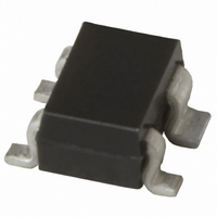
BGA 420 E6327 Infineon Technologies, BGA 420 E6327 Datasheet - Page 2

BGA 420 E6327
Manufacturer Part Number
BGA 420 E6327
Description
AMP SI-MMIC 6V 15MA SOT-343
Manufacturer
Infineon Technologies
Type
General Purpose Amplifierr
Datasheet
1.BGA_420_E6327.pdf
(8 pages)
Specifications of BGA 420 E6327
Noise Figure
2.3dB
Current - Supply
5.4mA ~ 8mA
Frequency
100MHz ~ 3GHz
Gain
13dB
P1db
-2.5dB
Package / Case
SC-70-4, SC-82-4, SOT-323-4, SOT-343
Rf Type
Cellular, GSM, CDMA, TDMA, UMTS
Test Frequency
1GHz
Voltage - Supply
3V ~ 6V
Supply Current
8 mA
Maximum Power Dissipation
90 mW
Maximum Operating Temperature
+ 150 C
Mounting Style
SMD/SMT
Minimum Operating Temperature
- 65 C
Number Of Channels
1 Channel
Lead Free Status / RoHS Status
Lead free / RoHS Compliant
Other names
BGA 420 E6327
BGA420E6327INTR
BGA420E6327XT
SP000011089
BGA420E6327INTR
BGA420E6327XT
SP000011089
Electrical Characteristics at T
Parameter
AC characteristics V
Device current
Insertion power gain
f = 0.1 GHz
f = 1 GHz
f = 1.8 GHz
Reverse isolation
f = 1.8 GHz
Noise figure
f = 0.1 GHz
f = 1 GHz
f = 1.8 GHz
Intercept point at the output
f = 1 GHz
1dB compression point
f = 1 GHz
Return loss input
f = 1.8 GHz
Return loss output
f = 1.8 GHz
Typical biasing configuration
Note: 1) Large-value capacitors should be connected from pin 4 to ground right at the device
2) The use of plated through holes right at pin 2 is essential for pc-board-applications. Thin
to provide a low impedance path.
boards are recommended to minimize the parasitic inductance to ground.
100 pF
RF IN
D
= 3 V, Z
10 nF
A
o
100 pF
= 25 °C, unless otherwise specified.
= 50
4
1
+
BGA 420
V
D
GND
2
3
2
Symbol
I
|S
S12
NF
IP
P
RL
RL
D
-1dB
21
3out
in
out
100 pF
|
2
min.
5.4
17
15
11
25
10
12
-6
8
-
-
-
RF OUT
EHA07386
Values
typ.
-2.5
6.7
1.9
2.2
2.3
19
17
13
28
13
11
16
max.
2.3
2.6
2.7
2007-07-12
8
-
-
-
-
-
-
-
-
BGA420
Unit
mA
dB
dBm
dB


