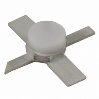
NBB-310-T1 RFMD, NBB-310-T1 Datasheet - Page 6

NBB-310-T1
Manufacturer Part Number
NBB-310-T1
Description
IC AMP MMIC GAAS 12GHZ 4-MICROX
Manufacturer
RFMD
Datasheet
1.NBB-310-T1.pdf
(12 pages)
Specifications of NBB-310-T1
Current - Supply
50mA
Frequency
0Hz ~ 12GHz
Gain
11dB ~ 11.5dB @ 4GHz ~ 8GHz
Noise Figure
4.9dB @ 3GHz
P1db
14.5dBm @ 8GHz
Package / Case
4-Micro-X
Rf Type
LMDS, VSAT, WLAN, UNII, DWDM, PTP PMP
Voltage - Supply
4.4V ~ 4.9V
Lead Free Status / RoHS Status
Lead free / RoHS Compliant
Test Frequency
-
Other names
689-1001-2
NBB-310TR13
NBB-310TR13
Available stocks
Company
Part Number
Manufacturer
Quantity
Price
Company:
Part Number:
NBB-310-T1
Manufacturer:
MPS
Quantity:
12 000
NBB-310
Die Attach
Die Wire Bonding
Notes
1
tion personnel to determine final visual acceptance of die product prior to shipping to customers.
2
material shift. However, due to the physical size of die-level product, RFMD does not guarantee that material will not shift dur-
ing transit, especially under extreme handling circumstances. Product replacement due to material shift will be at the discre-
tion of RFMD.
6 of 12
RFMD Document #6000152 - Die Product Final Visual Inspection Criteria. This document provides guidance for die inspec-
RFMD takes precautions to ensure that die product is shipped in accordance with quality standards established to minimize
• The die attach process mechanically attaches the die to the circuit substrate. In addition, the utilization of proper die
• Die should be mounted to a clean, flat surface. Epoxy or eutectic die attach are both acceptable attachment meth-
• All connections should be made on the topside of the die. It is essential to performance that the backside be well
• Some die utilize vias for effective grounding. Care must be exercised when mounting die to preclude excess run-out
• Electrical connections to the chip are made through wire bonds. Either wedge or ball bonding methods are accept-
• All bond wires should be made as short as possible.
attach processes electrically connect the ground to the trace on which the chip is mounted. It also establishes the
thermal path by which heat can leave the chip.
ods. Top and bottom metallization are gold. Conductive silver-filled epoxies are recommended. This procedure
involves the use of epoxy to form a joint between the backside gold of the chip and the metallized area of the sub-
strate.
grounded and that the length of topside interconnects be minimized.
on the topside.
able practices for wire bonding.
7628 Thorndike Road, Greensboro, NC 27409-9421 · For sales or technical
support, contact RFMD at (+1) 336-678-5570 or sales-support@rfmd.com.
Rev A11 DS070327


