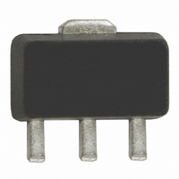
RF3376TR7 RFMD, RF3376TR7 Datasheet - Page 2

RF3376TR7
Manufacturer Part Number
RF3376TR7
Description
IC AMP HBT GAAS GEN-PUR SOT-89
Manufacturer
RFMD
Datasheet
1.RF3376TR7.pdf
(8 pages)
Specifications of RF3376TR7
Current - Supply
35mA ~ 40mA
Frequency
0Hz ~ 6GHz
Gain
18dB ~ 19.8dB
Noise Figure
2dB
P1db
9.5dBm ~ 11.5dBm
Package / Case
SOT-89
Rf Type
General Purpose
Test Frequency
2GHz
Voltage - Supply
3.4V ~ 3.5V
Lead Free Status / RoHS Status
Lead free / RoHS Compliant
Other names
689-1022-2
RF3376
2 of 8
Absolute Maximum Ratings
Input RF Power
Operating Ambient Temperature
Storage Temperature
I
Overall
Frequency Range
3dB Bandwidth
Gain
Noise Figure
Input VSWR
Output VSWR
Output IP
Output P
Reverse Isolation
Thermal
Theta
Maximum Measured Junction
Mean Time To Failures
Power Supply
Device Operating Voltage
Operating Current
Note 1: All specification and characterization data has been gathered on standard FR-4 evaluation boards. These evaluation boards are not
Note 2: The RF3376 must be operated at or below 40mA in order to achieve the thermal performance listed above. While the RF3376 may be
Note 3: Because of process variations from part to part, the current resulting from a fixed bias voltage will vary. As a result, caution should be
CC
Temperature at DC Bias
Conditions
optimized for frequencies above 2.5GHz. Performance above 2.5GHz may improve if a high performance PCB is used.
operated at higher bias currents, 35mA is the recommended bias to ensure the highest possible reliability and electrical performance.
used in designing fixed voltage bias circuits to ensure the worst case bias current does not exceed 40mA over all intended operating condi-
tions.
JC
1dB
3
Parameter
Parameter
7628 Thorndike Road, Greensboro, NC 27409-9421 · For sales or technical
support, contact RFMD at (+1) 336-678-5570 or sales-support@rfmd.com.
+22.0
+21.5
Min.
22.0
21.0
18.0
+9.5
+9.5
-60 to +150
-40 to +85
Rating
Specification
+3
40
DC to >6000
35000
+23.4
+24.4
+11.5
+11.5
Typ.
23.5
22.5
18.0
12.8
<2:1
<2:1
19.8
16.0
22.5
109
216
2.0
3.4
4.2
35
2
Max.
Unit
dBm
3.5
4.5
°C
mA
40
°C
Exceeding any one or a combination of the Absolute Maximum Rating conditions may
cause permanent damage to the device. Extended application of Absolute Maximum
Rating conditions to the device may reduce device reliability. Specified typical perfor-
mance or functional operation of the device under Absolute Maximum Rating condi-
tions is not implied.
RoHS status based on EUDirective2002/95/EC (at time of this document revision).
The information in this publication is believed to be accurate and reliable. However, no
responsibility is assumed by RF Micro Devices, Inc. ("RFMD") for its use, nor for any
infringement of patents, or other rights of third parties, resulting from its use. No
license is granted by implication or otherwise under any patent or patent rights of
RFMD. RFMD reserves the right to change component circuitry, recommended appli-
cation circuitry and specifications at any time without prior notice.
°C/W
years
Unit
dBm
dBm
dBm
dBm
MHz
GHz
mA
dB
dB
dB
dB
dB
dB
°C
V
v
Caution! ESD sensitive device.
T=25 °C, I
Freq=500MHz
Freq=1000MHz
Freq=2000MHz
Freq=3000MHz
Freq=4000MHz
Freq=6000MHz
Freq=2000MHz
In a 50Ω system, DC to 4500MHz
In a 50Ω system, DC to 6000MHz
Freq=1000MHz
Freq=2000MHz
Freq=1000MHz
Freq=2000MHz
Freq=2000MHz
I
T
T
With 22Ω bias resistor
At pin 8 with I
At evaluation board connector, I
See Note 2.
CC
CASE
CASE
=35mA, P
=+85°C
=+85°C
CC
=35mA (See Note 1.)
CC
DISS
=35mA
Condition
=110mW. (See Note 3.)
Rev A6 DS050524
CC
=35mA


