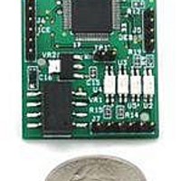
78M6612-EVM-1 Maxim Integrated Products, 78M6612-EVM-1 Datasheet - Page 46

78M6612-EVM-1
Manufacturer Part Number
78M6612-EVM-1
Description
BOARD EVAL 78M6612 AC-PMON
Manufacturer
Maxim Integrated Products
Type
PMIC Solutionsr
Datasheets
1.78M6612-IMF.pdf
(111 pages)
2.78M6612-EVM-1.pdf
(36 pages)
3.78M6612-EVM-1.pdf
(58 pages)
Specifications of 78M6612-EVM-1
Operating Supply Voltage
5 V
Product
Power Management Modules
Supply Current
10 A
Lead Free Status / RoHS Status
Lead free / RoHS Compliant
Control Relay
PFB_wb_Neg
PFB_wb_Pos
6612_OMU_S2+2_URT_V1_14 Firmware Description Document
46
Parameter
Mask_Reg
Mask_DIO
Threshold
Threshold
Threshold
Total_wb
Threshold
Total_nb
Min/Max
Control
Peak I
Peak I
Alarm
Alarm
Alarm
Alarm
MPU
Location
(hex)
E2
E3
E4
E5
E6
E7
F0
F1
mArms
mArms
LSB
–
–
–
–
–
–
00801FFF
00801FFF
+20.000
+20.000
Default
+0.700
-0.700
0
0
BIT1 – 1 Start/Stop MIN/MAX
recording.
BIT0 – 1 Reset MIN/MAX
registers before recording. Bit
autoclears.
Register). Only available if )F2 bit
this threshold will set an alarm (bit
Wideband Power Factor Negative
Threshold for Outlet 2. A positive
measured on Outlet 1 plus Outlet
measured on Outlet 1 plus Outlet
2 above which a flag must be set
2 above which a flag must be set
Wideband Power Factor Positive
18 of the Alarm Status Register).
alarm (bit 17 of the Alarm Status
wideband power factor less than
Status register. A “0” masks the
Alarm mask for bits in the Alarm
(DIO20). A “0” masks the alarm
negative wideband power factor
1 = Start
0 = Stop
Maximum Narrowband Current
Note: AC[1] = 1 inverts the bits
Threshold for Outlet 2. A less
than this threshold will set an
Maximum Wideband Current
Alarm mask for an alarm pin
alarm from the register bit.
(bit 19 of the Alarm Status
(bit 20 of the Alarm Status
Bit 1 (Relay for Outlet 2)
Bit 0 (Relay for Outlet 1)
0 = DIO19 = 0
1 = DIO19 =1
0 = DIO7 = 0
1 = DIO7 = 1
2 is set to 1.
from DIO20
Comment
Register).
Register).
above.
from the default to -0.6 then
masked then set as follows:
current threshold on Outlet
current threshold on Outlet
power factor threshold on
power factor threshold on
Amps then set as follows:
Amps then set as follows:
Outlet 2 is to be changed
Outlet 2 is to be changed
changed from the default
changed from the default
Stop MIN/MAX recording
If the negative wideband
If the positive wideband
Reset & Start MIN/MAX
from the default to +0.6
If the narrowband peak
value of 20 Amps to 30
value of 20 Amps to 30
If bits 0 and 1 are to be
1 plus Outlet 2 is to be
1 plus Outlet 2 is to be
If the wideband peak
then set as follows:
)E4=+30.000<CR>
)E5=+30.000<CR>
)E3=+0.600<CR>
>)E6=FFFFFFFC
)E2=-0.600<CR>
set as follows:
)AC=11<CR>
)AC=0x<CR>
recording.
Example
UG_6612_017
Rev. 1.0


