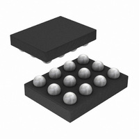
LM3530UME-25A/NOPB National Semiconductor, LM3530UME-25A/NOPB Datasheet - Page 13

LM3530UME-25A/NOPB
Manufacturer Part Number
LM3530UME-25A/NOPB
Description
IC LED DRVR PRGRAM I2C 10LED SMD
Manufacturer
National Semiconductor
Series
PowerWise®r
Datasheet
1.LM3530UME-40NOPB.pdf
(44 pages)
Specifications of LM3530UME-25A/NOPB
Topology
PWM, Step-Up (Boost)
Number Of Outputs
1
Internal Driver
Yes
Type - Primary
Backlight
Type - Secondary
White LED
Frequency
500kHz
Voltage - Supply
2.7 V ~ 5.5 V
Mounting Type
Surface Mount
Package / Case
12-XFBGA
Operating Temperature
-40°C ~ 85°C
Current - Output / Channel
Adjustable
Lead Free Status / RoHS Status
Lead free / RoHS Compliant
Voltage - Output
-
Other names
LM3530UME-25A/NOPBTR
Operational Description
The LM3530 utilizes an asynchronous step-up, current mode,
PWM controller and regulated current sink to provide an effi-
cient and accurate LED current for white LED bias. The device
powers a single series string of LEDs with output voltages of
up to 40V and a peak inductor current of typically 839mA. The
input active voltage range is from 2.7V to 5.5V.
STARTUP
An internal soft-start prevents large inrush currents during
startup that can cause excessive current spikes at the input.
For the typical application circuit (using a 10µH inductor, a
2.2µF input capacitor, and a 1µF output capacitor) the aver-
age input current during startup ramps from 0 to 300mA in
3ms. See Start Up Plots in the Typical Performance Charac-
teristics.
LIGHT LOAD OPERATION
The LM3530's boost converter operates in three modes: con-
tinuous conduction, discontinuous conduction, and skip
mode. Under heavy loads when the inductor current does not
reach zero before the end of the switching period, the device
switches at a constant frequency (500kHz typical). As the
output current decreases and the inductor current reaches
zero before the end of the switching period, the device oper-
ates in discontinuous conduction. At very light loads the
LM3530 will enter skip mode operation causing the switching
period to lengthen and the device to only switch as required
ALS OPERATION
The ambient light sensor input has a 0 to 1V operational input
voltage range. The Typical Application Circuit shows the
LM3530
APDS-9005) and the internal ALS Resistor Select Register
set to 0x44 (2.27kΩ). This circuit converts 0 to 1000 LUX light
into approximately a 0 to 850mV linear output voltage. The
voltage at the active ambient light sensor input (ALS1 or
ALS2) is compared against the 8 bit values programmed into
the Zone Boundary Registers (ZB0-ZB3). When the ambient
light sensor output crosses one of the ZB0 – ZB3 programmed
thresholds the internal ALS circuitry will smoothly transition
with
dual
ambient
FIGURE 3. Ambient Light Sensor Functional Block Diagram
light
sensors
(AVAGO,
13
to maintain regulation at the output. Light load operation pro-
vides for improved efficiency at lighter LED currents com-
pared to continuous and discontinuous conduction. This is
due to the pulsed frequency operation resulting in decreased
switching losses in the boost converter.
AMBIENT LIGHT SENSOR
The LM3530 incorporates a dual input Ambient Light Sensing
interface (ALS1 and ALS2) which translates an analog output
ambient light sensor to a user-specified brightness level. The
ambient light sensing circuit has 4 programmable boundaries
(ZB0 – ZB3) which define 5 ambient brightness zones. Each
ambient brightness zone corresponds to a programmable
brightness threshold (Z0T – Z4T). The ALS interface is pro-
grammable to accept the ambient light information from either
the highest voltage of ALS1 or ALS2, the average voltage of
ALS1 or ALS2, or selectable from either ALS1 or ALS2.
Furthermore, each ambient light sensing input (ALS1 or
ALS2) features 15 internal software selectable voltage setting
resistors. This allows the LM3530 the capability of interfacing
with a wide selection of ambient light sensors. Additionally,
the ALS inputs can be configured as high impedance, thus
providing for a true shutdown during low power modes. The
ALS resistors are selectable through the ALS Resistor Select
Register (see
agram of the ambient light sensor input. VSNS represents the
active input as described in
the LED current to the new 7 bit brightness level as pro-
grammed into the appropriate Zone Target Register (Z0T –
Z4T) (see
The ALS Configuration Register bits [6:5] programs which in-
put is the active input, bits [4:3] control the on/off state of the
ALS circuitry, and bits [2:0] control the ALS input averaging
time. Additionally, the ALS Information Register is a read-only
register which contains a flag (bit 3) which is set each time the
active ALS input changes to a new zone. This flag is reset
when the register is read back. Bits [2:0] of this register con-
tain the current active zone information.
Figure
Table
4).
9).
Figure 3
Table 6
shows a functional block di-
bits [6:5].
www.national.com
30086607


