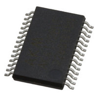
AK5384VFP AKM Semiconductor Inc, AK5384VFP Datasheet - Page 3

AK5384VFP
Manufacturer Part Number
AK5384VFP
Description
IC ADC AUDIO STER 24BIT 28VSOP
Manufacturer
AKM Semiconductor Inc
Type
ADCr
Datasheet
1.AK5384VFP.pdf
(21 pages)
Specifications of AK5384VFP
Resolution (bits)
24 b
Sampling Rate (per Second)
8k ~ 96k
Voltage Supply Source
Analog and Digital
Voltage - Supply
4.75 V ~ 5.25 V
Operating Temperature
-40°C ~ 85°C
Mounting Type
Surface Mount
Package / Case
28-LSSOP (0.220", 5.60mm)
Lead Free Status / RoHS Status
Lead free / RoHS Compliant
Data Interface
-
Other names
974-1031-2
AK5384VFP
AK5384VFP
Available stocks
Company
Part Number
Manufacturer
Quantity
Price
Company:
Part Number:
AK5384VFP-E2
Manufacturer:
ADI
Quantity:
2 120
ASAHI KASEI
Note: All digital input pins should not be left floating.
MS0225-E-00
No. Pin Name
10
11
12
13
14
15
16
17
18
19
20
21
22
23
24
25
26
27
28
1
2
3
4
5
6
7
8
9
LIN2+
LIN2
RIN2+
RIN2
TEST
VCOM
AVSS
AVDD
DIF
TDM1
TDM0
TDMIN
MCLK
OVF
LRCK
BICK
SDTO2
SDTO1
TVDD
DVDD
DVSS
PDN
CKS
M/S
RIN1
RIN1+
LIN1
LIN1+
I/O
I/O
I/O
O
O
O
O
I
I
I
I
I
-
-
I
I
I
I
-
-
-
I
I
I
I
I
I
I
I
Function
ADC2 Lch Positive Analog Input Pin
ADC2 Lch Negative Analog Input Pin
ADC2 Rch Positive Analog Input Pin
ADC2 Rch Negative Analog Input Pin
Test Pin
Common Voltage Output Pin, AVDD/2
Analog Ground Pin
Analog Power Supply Pin, 4.75 5.25V
Audio Interface Format Pin
TDM I/F BICK Frequency Select Pin
TDM I/F Format Enable Pin
TDM Data Input Pin
Master Clock Input Pin
Analog Input Overflow Detect Pin
Output Channel Clock Pin
Audio Serial Data Clock Pin
ADC2 Audio Serial Data Output Pin
ADC1 Audio Serial Data Output Pin
Output Buffer Power Supply Pin, 3.0 5.25V
Digital Power Supply Pin, 4.75 5.25V
Digital Ground Pin
Power-Down Mode Pin
Master Clock Select Pin
Master / Slave Mode Pin
ADC1 Rch Negative Analog Input Pin
ADC1 Rch Positive Analog Input Pin
ADC1 Lch Negative Analog Input Pin
ADC1 Lch Positive Analog Input Pin
Normally connected to AVSS with a 0.1 F ceramic capacitor in parallel with an
electrolytic capacitor less than 2.2 F.
“L” : 24bit MSB justified, “H” : 24bit I
“L” : 256fs, “H” : 128fs
“L” : Normal Mode, “H” : TDM Mode
This pin goes to “H” if one of four analog inputs overflows.
“L” Output in Master Mode at Power-down mode.
“L” Output in Master Mode at Power-down mode.
“L” Output at Power-down mode.
“L” Output at Power-down mode.
When “L”, the circuit is in power-down mode.
The AK5384 should always be reset upon power-up.
“L” : 256fs, “H” : 512fs
This pin is enabled in Master Mode.
“L” : Slave Mode, “H” : Master Mode
(Connected to AVSS)
PIN/FUNCTION
- 3 -
2
S Compatible
[AK5384]
2003/05


