SMP100LC-25 STMicroelectronics, SMP100LC-25 Datasheet - Page 5
SMP100LC-25
Manufacturer Part Number
SMP100LC-25
Description
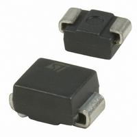
IC TVS BIDIRECT 25V 100A SMB
Manufacturer
STMicroelectronics
Series
TRISIL™r
Datasheet
1.SMP100LC-35.pdf
(12 pages)
Specifications of SMP100LC-25
Voltage - Reverse Standoff (typ)
22V
Voltage - Breakdown
25V
Polarization
Bidirectional
Mounting Type
Surface Mount
Package / Case
DO-214AA, SMB
Polarity
Bidirectional
Operating Voltage
22 V
Breakdown Voltage
25 V
Termination Style
SMD/SMT
Peak Surge Current
100 A
Dimensions
5.6 mm W x 4.6 mm L x 2.45 mm H
Lead Free Status / RoHS Status
Lead free / RoHS Compliant
Power (watts)
-
Lead Free Status / Rohs Status
Lead free / RoHS Compliant
Other names
497-3719-2
Available stocks
Company
Part Number
Manufacturer
Quantity
Price
Company:

Part Number:
SMP100LC-25
Manufacturer:
ST
Quantity:
54 000
Part Number:
SMP100LC-25
Manufacturer:
ST
Quantity:
20 000


SMP100LC
2
Figure 7.
0.01
0.1
1
1E-3
Z
th(j-a)
Printed circuit board - FR4,
copper thickness = 35µm,
recommended pad layout
/R
1E-2
th(j-a)
Application information
In wireline applications, analog or digital, both central office and subscriber sides have to be
protected. This function is assumed by a combined series / parallel protection stage.
Figure 9.
In such a stage, parallel function is assumed by one or several Trisil, and is used to protect
against short duration surge (lightning). During this kind of surges the Trisil limits the voltage
across the device to be protected at its break over value and then fires. The fuse assumes
the series function, and is used to protect the module against long duration or very high
current mains disturbances (50/60Hz). It acts by safe circuit opening. Lightning surge and
mains disturbance surges are defined by standards like GR1089, FCC part 68, ITU-T K20.
Figure 10. Typical circuits
Variation of thermal impedance
junction to ambient versus pulse
duration
1E-1
t (s)
p
Examples of protection stages for line cards
1E+0
Fuse TCP 1.25A
Typical circuit for subscriber side
Line
1E+1
Ex. Analog line card
1E+2
Doc ID 7050 Rev 13
SMP100LC-xxx
5E+2
T1
T2
Ring
relay
Figure 8.
1.4
1.2
1.0
0.8
0.6
0.4
0.2
0.0
1
C [V ] / C [V =2V]
Ring L
Tip L
Gnd
R
Fuse TCP 1.25A
Fuse TCP 1.25A
Typical circuit for central office side
Line
2
Ex. xDSL line card or terminal
Relative variation of junction
capacitance versus reverse voltage
applied (typical values)
R
5
10
V (V)
R
Application information
20
SMP100LC-xxx
SMP100LC-xxx
Tip S
Gnd
Ring S
50
100
V
T = 25°C
F =1MHz
RMS
j
= 1V
300
5/12
Related parts for SMP100LC-25
Image
Part Number
Description
Manufacturer
Datasheet
Request
R

Part Number:
Description:
Manufacturer:
STMicroelectronics
Datasheet:
Part Number:
Description:
Manufacturer:
STMicroelectronics
Datasheet:
Part Number:
Description:
Manufacturer:
STMicroelectronics
Datasheet:
Part Number:
Description:
Manufacturer:
STMicroelectronics
Datasheet:
Part Number:
Description:
Manufacturer:
STMicroelectronics
Datasheet:
Part Number:
Description:
Manufacturer:
STMicroelectronics
Datasheet:

Part Number:
Description:
Diacs RO 511-SMP100LC-140 SMB 140V TRISIL
Manufacturer:
STMicroelectronics
Part Number:
Description:
Diacs 65V 50uA Bidirect
Manufacturer:
STMicroelectronics
Datasheet:
Part Number:
Description:
Diacs 120V 50uA Bidirect
Manufacturer:
STMicroelectronics
Datasheet:
Part Number:
Description:
Diacs RO 511-SMP1001C-270 SMB 270V TRISIL
Manufacturer:
STMicroelectronics
Datasheet:
Part Number:
Description:
Diacs 200V 50uA Bidirect
Manufacturer:
STMicroelectronics
Datasheet:

Part Number:
Description:
COMMUNICATION EQUIPMENT PROTECTION: TRISIL TM
Manufacturer:
STMICROELECTRONICS [STMicroelectronics]
Datasheet:
Part Number:
Description:
COMMUNICATION EQUIPMENT PROTECTION: TRISIL TM
Manufacturer:
STMicroelectronics
Datasheet: