ECJ-2FB1H823K Panasonic - ECG, ECJ-2FB1H823K Datasheet - Page 5
ECJ-2FB1H823K
Manufacturer Part Number
ECJ-2FB1H823K
Description
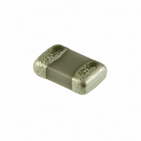
CAP .082UF 50V CERAMIC X7R 0805
Manufacturer
Panasonic - ECG
Series
ECJr
Datasheets
1.ECJ-RVB1H332M.pdf
(6 pages)
2.ECJ-RVB1H332M.pdf
(2 pages)
3.ECJ-RVB1H332M.pdf
(1 pages)
4.ECJ-RVB1H332M.pdf
(3 pages)
5.ECJ-0EB1H102K.pdf
(12 pages)
Specifications of ECJ-2FB1H823K
Capacitance
0.082µF
Voltage - Rated
50V
Tolerance
±10%
Temperature Coefficient
X7R
Mounting Type
Surface Mount, MLCC
Operating Temperature
-55°C ~ 125°C
Features
Low ESR
Applications
General Purpose
Package / Case
0805 (2012 Metric)
Size / Dimension
0.079" L x 0.049" W (2.00mm x 1.25mm)
Thickness
1.25mm
Lead Free Status / RoHS Status
Lead free / RoHS Compliant
Ratings
-
Lead Spacing
-
Other names
ECJ-2FB1H823K
ECJ2FB1H823K
ECJ2FB1H823K
PCC2451TR
Q1989096D
ECJ2FB1H823K
ECJ2FB1H823K
PCC2451TR
Q1989096D


(✽1) Heat treatment:1 h of heat treatment at 150+0/–10 °C followed by 48±4 h recovery under standard conditions
(✽2) Voltage treatment:1 h of voltage treatment under the specifi ed temperature and voltage for testing followed by 48±4 h of recovery under
Design and specifi cations are each subject to change without notice. Ask factory for the current technical specifi cations before purchase and/or use.
Should a safety concern arise regarding this product, please be sure to contact us immediately.
Damp Heat
Load
High
Temperature
Load
standard conditions
Item
Appearance:
Capacitance change:
Q:
tan δ:
IR:
Appearance:
Capacitance change:
Q:
tan δ:
IR:
No mechanical damage
Within ±7.5 % or ±0.75 pF
whichever is larger.
C<30 pF:Q >100+10C/3
30 pF<C <1000 pF:Q >200
C>1000 pF:tan δ< 0.004
(C:Nominal capacitance in pF)
500 M
Whichever is less.
(C:Nominal capacitance in µF)
No mechanical damage
Within ±3 % or ±0.3 pF
whichever is larger.
C<10 pF:Q >200+10C
10 pF<C<30 pF:Q >275+5C/2
30 pF<C <1000 pF:Q > 350
C>1000 pF:tan δ< 0.004
C:Nominal capacitance in pF
1000 M
Whichever is less.
C:Nominal capacitance in µF
Class 1
or 25/C (M )
or 50/C (M )
Specifi cation
Appearance:
Capacitance change:
tan δ:
IR:
Please see the technical
specifi cations for details.
Appearance:
Capacitance change:
tan δ:
IR:
Please see the technical
specifi cations for details.
No mechanical damage
Temp. Char.
B, X7R, X5R: Within ±20 %
F, Y5V: Within ±30 %
Temp. Char.
B, X7R, X5R: 0.25 max.
F, Y5V: 0.3 max.
500 M
Whichever is less.
Note:5/C (M ) min. for
DC 10 V max.
C:Nominal capacitance in µF
No mechanical damage
Temp. Char.
B, X7R, X5R: Within ±20 %
F, Y5V: Within ±30 %
Temp. Char.
B, X7R, X5R: 0.25 max.
F, Y5V: 0.3 max.
1000 MΩ or 50/C (M )
Whichever is less.
Note:10/C (M ) min. for
DC 10 V max.
C:Nominal capacitance in µF
Multilayer Ceramic Capacitors(For General Usage)
– EC12 –
Class 2
or 25/C (M )
Preconditioning:Voltage treatment/Class 2
Temperature:40±2 °C
Relative humidity:90 to 95 %
Applied voltage:Rated voltage
Charge/discharge current: 50 mA max.
Test pe ri od:500+24/0 h
Recovery (Standard condition)
Preconditioning:Voltage treatment/Class 2
Temperature:
Applied voltage:
Please see the technical specifi cations
for details.
Charge/discharge current: 50 mA max.
Test period:1000+48/0 h
Recovery (Standard condition)
Class 1:24±2 h
Class 2:48±4 h
Maximum operating temp. ±3 °C
(1) Rated voltage ×200 %
(2) Rated voltage ×100 %
Class 1:24±2 h
Class 2:48±4 h
Test Method
00
Sep. 2008
(✽2)
(✽2)
Related parts for ECJ-2FB1H823K
Image
Part Number
Description
Manufacturer
Datasheet
Request
R

Part Number:
Description:
CAP ARRAY 22PF 50V NP0 0504
Manufacturer:
Panasonic - ECG
Datasheet:
Part Number:
Description:
CAP ARRAY 10PF 50V NP0 0504
Manufacturer:
Panasonic - ECG
Datasheet:
Part Number:
Description:
CAP ARRAY 100PF 50V NP0 0504
Manufacturer:
Panasonic - ECG
Datasheet:
Part Number:
Description:
CAP ARRAY 47PF 50V NP0 0504
Manufacturer:
Panasonic - ECG
Datasheet:
Part Number:
Description:
CAP ARRAY 2.2UF 6.3V X5R 0504
Manufacturer:
Panasonic - ECG
Datasheet:
Part Number:
Description:
CAP ARRAY .1UF 10V X5R 0504
Manufacturer:
Panasonic - ECG
Datasheet:
Part Number:
Description:
CAP ARRAY 1UF 6.3V X5R 0504
Manufacturer:
Panasonic - ECG
Datasheet:
Part Number:
Description:
CAP ARRAY 1UF 6.3V X5R 0504
Manufacturer:
Panasonic - ECG
Datasheet:
Part Number:
Description:
CAP ARRAY 1UF 10V X5R 0504
Manufacturer:
Panasonic - ECG
Datasheet:
Part Number:
Description:
CAP ARRAY 1UF 10V X5R 0504
Manufacturer:
Panasonic - ECG
Datasheet:


Part Number:
Description:
MICROPHONE OMNI 6X2.2MM W/CAP
Manufacturer:
Panasonic - ECG
Datasheet:

Part Number:
Description:
CAP .01UF 100V PEN FILM 1210 5%
Manufacturer:
Panasonic - ECG
Datasheet:

Part Number:
Description:
FILTER LINE 23.3MH 2A
Manufacturer:
Panasonic - ECG
Datasheet:

Part Number:
Description:
SAW FILTER PCS 1960 MHZ 50/150
Manufacturer:
Panasonic - ECG
Datasheet: