E3X-A11 Omron, E3X-A11 Datasheet - Page 10
E3X-A11
Manufacturer Part Number
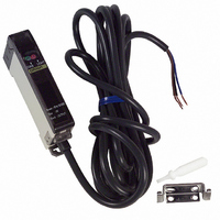
E3X-A11
Description
SENSOR PHOTO AMP USE W/E32 FIBER
Manufacturer
Omron
Series
E3Xr
Type
Fiber Optic Photoelectric Sensorr
Datasheet
1.E3X-A21.pdf
(17 pages)
Specifications of E3X-A11
Amplifier Type
Standard
Voltage - Supply
10 V ~ 30 V
Output Type
NPN
Current - Supply
35mA
Mounting Type
DIN Rail
Features
High Performance Amplifier Has Fast
Light Source
Pulse Modulated Red LED
Connection
3 Conductor Cable
Output Configuration
NPN
Lead Free Status / RoHS Status
Contains lead / RoHS compliant by exemption
Lead Free Status / RoHS Status
Contains lead / RoHS compliant by exemption, Lead free / RoHS Compliant
Other names
E3XA11
Z1114
Z1114
Available stocks
Company
Part Number
Manufacturer
Quantity
Price
Company:

Part Number:
E3X-A11-8
Manufacturer:
OMRON
Quantity:
473


E3X
Detection of Plate Level Differences
(If detection is impossible with the hysteresis value set to
maximum)
Large hysteresis
differential
VARIABLE HYSTERESIS FUNCTION (E3X-H11)
Detecting operation is not stable
because zone B is within the
hysteresis differential range.
Decide the position of
the fiber head and that
of the sensing object in
zone A.
Locate the head in
zone A and turn the
sensitivity adjuster
counterclockwise slowly
until the stable operation
indicator and light reception
indicator are OFF (i.e.,
position E as shown in
the illustration).
Set both the sensitivity
adjuster and hysteresis
adjuster to maximum.
head is located in zone B,
light reception indicator
Reflection
of light
Detection is possible
When the
is lit.
YES
S
ON
A
L
Unstable
B
NO
S
Sensitivity
ON
OFF
adjuster
1
min
L
SENS
(E)
1
min
max
SENS
s
max
s
hysteresis adjuster counterclockwise slowly
Reduce the sensitivity of the E3X
with the sensitivity adjuster and turn
off zone B.
Reflection
of light
is located in zone B and the light
Set the hysteresis adjuster
to the point where the light
reception indicator is lit
(i.e., position E as shown
in the illustration.)
and make sure that the light
indicator is lit when the head
is OFF when the head is
in zone B and turn the
reception indicator
The light reception
reception indicator
located in zone A.
Locate the head
Hysteresis
differential
Unstable
adjuster
min
is lit.
A
11
max
YES
Refer to the following when using the hysteresis adjuster.
S
YES
OFF
S
B
L
L
(H)
ON
OFF
min
B
max
NO
NO
S
S
min
Small hysteresis differential
(example)
L
max
L
Reduce the hysteresis value with
the hysteresis adjuster so that zone
A will be ON.
Locate the head in
zone A and turn the
sensitivity adjuster
clockwise until the
stable operation
indicator and light
reception indicator
are OFF (i.e., position
F as shown in the
illustration.)
Set the hysteresis
adjuster to maximum.
Locate the head in
zone A and turn the
sensitivity adjuster
counterclockwise
until the light reception
indicator and stable
operation indicator are
OFF (i.e., position O
as shown in
the illustration).
Reflection
of light
A
ON
A
(G)
(G)
OFF
B
min
(F)
(E)
1
min
1
min
SENS
SENS
max
E3X
max
max
s
s
ON
OFF
11
Related parts for E3X-A11
Image
Part Number
Description
Manufacturer
Datasheet
Request
R

Part Number:
Description:
EXPANDABLE A/D NPN FO AMP
Manufacturer:
Omron
Datasheet:

Part Number:
Description:
EXPANDABLE A/D PNP FO AMP
Manufacturer:
Omron
Datasheet:

Part Number:
Description:
PREWIRED A/D PNP FO AMP
Manufacturer:
Omron
Datasheet:

Part Number:
Description:
PREWIRED A/D NPN FO AMP
Manufacturer:
Omron
Datasheet:

Part Number:
Description:
Industrial Photoelectric Sensors Power + input conn Master 4 cond 2M
Manufacturer:
Omron
Datasheet:
Part Number:
Description:
Industrial Photoelectric Sensors For additional amps Slave 2 cond 2M
Manufacturer:
Omron
Datasheet:

Part Number:
Description:
SENSOR PHOTOAMP FIBER 2M CBL
Manufacturer:
Omron
Datasheet:

Part Number:
Description:
SENSOR PHOTO AMP FIBEROPTC W/TMR
Manufacturer:
Omron
Datasheet:
Part Number:
Description:
RED LED NPN PREWIRE PTUNE
Manufacturer:
Omron
Datasheet:

Part Number:
Description:
G6S-2GLow Signal Relay
Manufacturer:
Omron Corporation
Datasheet:
Part Number:
Description:
Compact, Low-cost, SSR Switching 5 to 20 A
Manufacturer:
Omron Corporation
Datasheet:
Part Number:
Description:
Manufacturer:
Omron Corporation
Datasheet: