E2CY-T11 Omron, E2CY-T11 Datasheet - Page 4
E2CY-T11
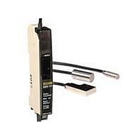
Manufacturer Part Number
E2CY-T11
Description
AMP 12-24VDC 3-WIRE NPN FOR E2CY
Manufacturer
Omron
Series
E2CYr
Specifications of E2CY-T11
Amplifier Type
Standard
Voltage - Supply
12 V ~ 24 V
Output Type
NPN
Current - Supply
40mA
Mounting Type
Bracket Mount
Lead Free Status / RoHS Status
Lead free / RoHS Compliant
Other names
E2CYT11


I/O Circuit Diagrams
Connection
Nomenclature
Amplifier Units
Indicators
Operation Indicator (Orange)
The operating indicator will turn ON when the control output is ON.
Excess Gain Level Indicators (Green and Orange)
The excess gain level indicators will be ON according to the distance
of the sensing object as shown at the right.
Fine-tuning indicator (green)
Operation indicator (orange)
Operation mode
Sensors
(Sensor Head mounting end)
(3) Output Mode Selector
(2) Resolution Selector
NO
NC
(Pre-wired cable end)
Shield
Line
Sensing object
Amplifier Unit
Operation
indicator (orange)
Output
transistor
Sensing object
Amplifier Unit
Operation
indicator (orange)
Sensor cable connecting
screws (M2.6)
Excess gain level indicators (green)
Excess gain level indicators (orange)
TEACH button
Output
transistor
(1) Operation Mode Selector
Amplifier Units
Timing Chart
Not present
Not present
Present
Present
OFF
OFF
OFF
OFF
ON
ON
ON
ON
Orange
Brown
Black
Blue
Position of sensing object
OFF
Lit orange
Lit green
(1) Operation Mode Selector
AUTO Mode: The sensitivity is automatically adjusted within a range
T Mode:
RUN Mode:
(2) Resolution Selector
If the E2CY often has a teaching error when detecting fine
differences, set the resolution selector to FINE. The response speed
will drop but improvement in the sensing precision of the E2CY can
be expected.
(3) Output Mode Selector
Used to select the transistor mode of the NPN open-collector output.
NO: Normally open output (Output transistor will turn ON if a sensing
NC: Normally closed output (Output transistor will turn ON if a
Excess Gain Level Indicators
Threshold
object is present.)
sensing object is not present.)
level
12 to 24 VDC
Control output
0 V
Self-diagnostic output
Orange
Green
*1. All indicators will be ON if the sensing object is at a position
*2. All indicators will be OFF if the sensing object is at a position
Near
of approximately 80% of the preset sensing distance.
of approximately 110% of the reset distance.
of approximately 80% to 110% of the rated sensing
distance. Except for the E2CY-C1R5A-1, which is
adjusted within approximately 60% to 110% of the
rated sensing distance.
This mode is used when adjusting the sensitivity of the
Sensor.
(The output transistor does not operate in this mode.)
This mode is used for the normal operation of the
Sensor.
*1
Proximity
Sensor
circuit
main
4.7 Ω
Output circuit
39 V
39 V
Brown
Black
Output
Blue
Orange
12 to 24 VDC
Load
Self-diagnostic
output
100 mA max.
100 mA
max.
0 V
E2CY
*2
Far
4
Related parts for E2CY-T11
Image
Part Number
Description
Manufacturer
Datasheet
Request
R

Part Number:
Description:
Proximity Sensors NON-FERROUS PROX HEA D FLAT
Manufacturer:
Omron
Datasheet:

Part Number:
Description:
Proximity Sensors NON-FERROUS PROX HEA D M5
Manufacturer:
Omron
Datasheet:
Part Number:
Description:
Proximity Sensors NON-FERROUS PROX HEA D 8MM DMTR
Manufacturer:
Omron
Datasheet:
Part Number:
Description:
Proximity Sensors E2CY-C1R5A SPECIAL W 3M CABLE
Manufacturer:
Omron

Part Number:
Description:
AMP NPN 10-30VDC FOR E2C PROX
Manufacturer:
Omron
Datasheet:

Part Number:
Description:
AMP NPN 10-30VDC FOR E2C-CR5B
Manufacturer:
Omron
Datasheet:
Part Number:
Description:
AMP PNP 10-30VDC FOR E2C PROX
Manufacturer:
Omron
Datasheet:
Part Number:
Description:
AMP PNP 10-30VDC FOR E2C-CR5B
Manufacturer:
Omron
Datasheet:
Part Number:
Description:
AMP 10-30VDC NPN/PNP FOR E2C
Manufacturer:
Omron
Datasheet:

Part Number:
Description:
DC AMP NPN FOR E2C PROX
Manufacturer:
Omron
Datasheet:
Part Number:
Description:
DC AMP For M8 E2C-H HiTemp PRX
Manufacturer:
Omron
Datasheet:
Part Number:
Description:
DC AMP, M18 E2C-H HiTemp PROX
Manufacturer:
Omron
Datasheet:
Part Number:
Description:
SEP.AMP.PROX. M18, 10mm DIST
Manufacturer:
Omron
Datasheet: