E3X-NA51 2M Omron, E3X-NA51 2M Datasheet - Page 19
E3X-NA51 2M
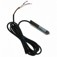
Manufacturer Part Number
E3X-NA51 2M
Description
SENSOR PHOTOAMP FIBER 2M CBL
Manufacturer
Omron
Series
E3X-NAr
Type
General Purposer
Specifications of E3X-NA51 2M
Amplifier Type
Standard
Voltage - Supply
12 V ~ 24 V
Output Type
PNP
Current - Supply
35mA
Mounting Type
DIN Rail
Fiber Optic Sensor Type
General Purpose
Rohs Compliant
Yes
Lead Free Status / RoHS Status
Lead free / RoHS Compliant
Lead Free Status / RoHS Status
Lead free / RoHS Compliant, Lead free / RoHS Compliant
Other names
E3X-NA51-2M
E3XNA512M
Z2941
E3XNA512M
Z2941


Securing Fibers
The E X Fiber Unit uses a one-touch locking mechanism. Use the
following methods to attach and remove Fiber Units.
(1) Attaching Fibers
Open the protective cover, insert the fiber up to the insertion mark on
the side of the Fiber Unit, and then lower the lock lever.
<Fiber Using the E39-F9 Attachment>
● Adjustments
Optical Axis Adjustment
Move the Photoelectric Sensor both vertically and horizontally and set
it in the center of the range in which the operation indicator is lit or not
lit. For the E S-C, the optical axis and the mechanical axis are the
same, so the optical axis can be easily adjusted by aligning the
mechanical axis.
Lock lever
Fiber
Emitter
Fiber Unit
Fiber insertion mark
Receiver
http://www.ia.omron.com/
1 mm
mm
1
2
Locked
position
l
Incident indicator or Operation indicator
ON
Optimum value
Incident indicator or Operation indicator
ON
mm
OFF
OFF
Insertion
position
Lock released position
Protective cover
Photoelectric Sensors Technical Guide
<Fibers That Cannot Be Free-cut (with Sleeves)>
(2) Removing Fibers
Open the protective cover, lift up the lock lever, and pull out the fibers.
Optical axis:
Mechanical axis: The axis perpendicular to the center of the lens.
Note:1.To maintain the fiber characteristics, make sure that the lock
2. Lock and unlock the fibers at an ambient temperature of
is released before removing the fibers.
−
(c)Copyright OMRON Corporation 2007 All Rights Reserved.
10 to 40°C.
Locked position
Emission beam
Emitter
The axis from the center of the lens to the center of
the beam for the Emitter and the axis from the
center of the lens to the center of the reception area
for the Receiver.
1 mm
Optical axis
Lock released
position
mm
Mechanical axis
Optical axis
Reception area
Protective cover
Receiver
C-5
Related parts for E3X-NA51 2M
Image
Part Number
Description
Manufacturer
Datasheet
Request
R

Part Number:
Description:
CONN READY NPN GEN PURPOSE FO
Manufacturer:
Omron
Datasheet:
Part Number:
Description:
CONN READY PNP GEN PURPOSE FO
Manufacturer:
Omron
Datasheet:
Part Number:
Description:
PNP GREEN LED GEN PURPOSE FOA
Manufacturer:
Omron
Datasheet:
Part Number:
Description:
AMANUAL FA NPN RED M8 CONN
Manufacturer:
Omron
Datasheet:

Part Number:
Description:
NPN GEN PURPOSE FO AMP
Manufacturer:
Omron
Datasheet:
Part Number:
Description:
PNP GEN PURPOSE FO AMP
Manufacturer:
Omron
Datasheet:

Part Number:
Description:
SENSOR PHOTO AMP FIBEROPTC W/TMR
Manufacturer:
Omron
Datasheet:
Part Number:
Description:
RED LED NPN PREWIRE PTUNE
Manufacturer:
Omron
Datasheet:
Part Number:
Description:
LIMITED FUNC AMP NPN CONN
Manufacturer:
Omron
Datasheet:

Part Number:
Description:
G6S-2GLow Signal Relay
Manufacturer:
Omron Corporation
Datasheet:
Part Number:
Description:
Compact, Low-cost, SSR Switching 5 to 20 A
Manufacturer:
Omron Corporation
Datasheet:
Part Number:
Description:
Manufacturer:
Omron Corporation
Datasheet: