414 Switchcraft Inc., 414 Datasheet - Page 69
Specifications of 414
Rohs Information
Switchcraft RoHS Info.
Connector Type
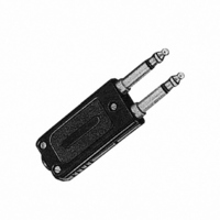
Phone Twin Plug
Gender
Male
Signal Lines
Stereo
Plug/mating Plug Diameter
6.35mm (0.250", 1/4") - Headphone
Number Of Positions/contacts
2 Sets of 3 Conductors, 6 Contacts
Internal Switch(s)
Does Not Contain Switch
Mounting Type
Free Hanging (In-Line)
Termination
Screw
Shielding
Unshielded
Color
Black
Number Of Ports
2Port
Body Orientation
Straight
Number Of Terminals
6
Mounting Style
Cable
Standard
1/4 in
Termination Style
Screw
Contact Plating
Tin
Contact Material
Copper Alloy
Lead Free Status / RoHS Status
Lead free / RoHS Compliant
Features
-
Lead Free Status / Rohs Status
Lead free / RoHS Compliant
Available stocks
Company
Part Number
Manufacturer
Quantity
Price
Company:

Part Number:
414-301A
Manufacturer:
AMI
Quantity:
6 229
Company:
Part Number:
414-41-204-41-117000
Manufacturer:
Mill-Max Manufacturing Corp.
Quantity:
418
Company:
Part Number:
414-41-206-41-117000
Manufacturer:
Mill-Max Manufacturing Corp.
Quantity:
228
Company:
Part Number:
414-41-208-41-117000
Manufacturer:
Mill-Max Manufacturing Corp.
Quantity:
330
Company:
Part Number:
414-41-210-41-117000
Manufacturer:
Mill-Max Manufacturing Corp.
Quantity:
459


64
w w w . s w i t c h c r a f t . c o m
CONNECTORS & RECEPTACLES
SLIM-LINE CONNECTORS
SLIM-LINE CONNECTORS
SL18 RECEPTACLES
Front of Panel Mount
SL MALE RECEPTACLES
SL FEMALE RECEPTACLES
SLIM-LINE CONNECTORS (continued)
Front of panel mount; 2 through 5 pins (male) or 2 through
5 contacts (female). Also 2-, 3- and 4-contact insert with
3 shunted (N.C.) contacts. Mounting locknut (Part Number
SL01), lockwasher (Part Number SL02), and flat washer
(Part Number SL03) supplied.
Part Number
Part Number
SL182M
SL183M
SL184M
SL185M
SL182F
SL183F
SL184F
SL185F
(17.7)
.696
Contacts
PANEL HOLE
Pins
2
3
4
5
2
3
4
5
Arrangements
SL183FS (typical)
Arrangements
DIMENSIONS ARE FOR REFERENCE ONLY
Contact
Pin
1
2
3
4
A
B
C
D
INSTALLING CABLE CLAMP ON INSERT
To install cable clamp on any insert:
1. Position insert approximately as shown in the diagram.
2. Hold clamp at approximately 30° angle (as shown). Place
3. Press center finger forward into slot and reduce angle of
Cable Clamp SL04
tip of clamp center finger into slot under molded ring “A”.
Note position of notch on insert in relation to slot.
clamp until clamp shoulders seat just ahead of molded
barrier on rear of insert “B”.
MOLDED
RING
“A”
INSERT
NOTCH
ON
(mm)
Note: Contact your Switchcraft Representative for price and delivery
Inch
PHONE: 773 792 - 2700
® Registered trademark of Switchcraft, Inc.
INSERT
“B”
CABLE
CLAMP
Related parts for 414
Image
Part Number
Description
Manufacturer
Datasheet
Request
R

Part Number:
Description:
CONN JACK MINI PHONE 2COND
Manufacturer:
Switchcraft Inc.
Datasheet:

Part Number:
Description:
CONN PLUG PHONE 1/4" 2POS RED
Manufacturer:
Switchcraft Inc.
Datasheet:

Part Number:
Description:
CONN PLUG 2-COND 1/4" PHONE SLD
Manufacturer:
Switchcraft Inc.
Datasheet:

Part Number:
Description:
CONN PLUG PHONE SILENT 2-COND
Manufacturer:
Switchcraft Inc.
Datasheet:

Part Number:
Description:
THICK PANEL/GOLD PLA
Manufacturer:
Switchcraft Inc.
Datasheet:

Part Number:
Description:
CONN PHONE JACK 2COND 1/4" OPEN
Manufacturer:
Switchcraft Inc.
Datasheet:
Part Number:
Description:
CONN JACK PHONE 1/4" 2POS W/HDWR
Manufacturer:
Switchcraft Inc.
Datasheet:

Part Number:
Description:
CONN PLUG PHONE .206" 2POS BLACK
Manufacturer:
Switchcraft Inc.
Datasheet:
Part Number:
Description:
CONN PLUG PHONE 1/4" FLAT 2POS
Manufacturer:
Switchcraft Inc.
Datasheet:

Part Number:
Description:
CONN PLUG FLAT PHONE 1/4" 3-COND
Manufacturer:
Switchcraft Inc.
Datasheet:

Part Number:
Description:
PHONE T-JACK PANEL .25" STD SGL
Manufacturer:
Switchcraft Inc.
Datasheet:

Part Number:
Description:
CONN JACK PANEL 96POS W/O JACK
Manufacturer:
Switchcraft Inc.
Datasheet:
Part Number:
Description:
CONN PLUG PHONE .206" 3POS BLACK
Manufacturer:
Switchcraft Inc.
Datasheet:

Part Number:
Description:
CONN JACK 1/4" 3-COND IN-LINE
Manufacturer:
Switchcraft Inc.
Datasheet:

Part Number:
Description:
CONN PLUG AUDIO PHONE 3COND BLK
Manufacturer:
Switchcraft Inc.
Datasheet: