PR01000101309JR500 Vishay, PR01000101309JR500 Datasheet - Page 13
PR01000101309JR500
Manufacturer Part Number
PR01000101309JR500
Description
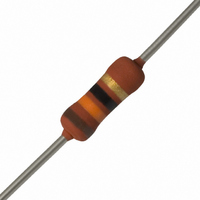
RES 13 OHM METAL FILM 1W 5%
Manufacturer
Vishay
Series
PR01r
Type
High power in small packagesr
Specifications of PR01000101309JR500
Resistance
13 Ohms
Power Rating
1 Watt
Voltage Rating
350 Volts
Temperature Coefficient
±250ppm/°C
Resistance (ohms)
13
Power (watts)
1W
Composition
Metal Film
Features
Flame Retardant Coating
Tolerance
±5%
Size / Dimension
0.098" Dia x 0.256" L (2.50mm x 6.50mm)
Lead Style
Through Hole
Package / Case
Axial
Resistance In Ohms
13.0
Case
Axial
Termination Style
Axial
Operating Temperature Range
- 55 C to + 175 C
Dimensions
2.5 mm Dia. x 6.5 mm L
Resistance Tolerance
± 5%
Resistor Element Material
Metal Film
Lead Free Status / RoHS Status
Lead free / RoHS Compliant
Height
-
Lead Free Status / Rohs Status
Lead free / RoHS Compliant
Other names
5073NW13R00J12AFX
PPC13W-1TR
PPC13W-1TR


PR01/02/03
Vishay BCcomponents
Application Information
TESTS AND REQUIREMENTS
Essentially all tests are carried out in accordance with
IEC 60115-1 specification, category LCT/UCT/56 (rated
temperature range: Lower Category Temperature, Upper
Category Temperature; damp heat, long term, 56 days).
The tests are carried out in accordance with IEC 60068-2-xx
Test Method under standard atmospheric conditions
according to IEC 60068-1, 5.3.
www.vishay.com
122
CLAUSE
TEST PROCEDURES AND REQUIREMENTS
4.4.1
4.4.2
4.5
4.18
4.29
60115-1
IEC
METHOD
60068-2-
20 (Tb)
45 (Xa)
TEST
IEC
10
10
R
Z
10
10
1
-1
-2
2
1
Dimensions (outline)
page for measuring
Component solvent
Visual examination
(refer note on first
soldering heat
Resistance to
Resistance
resistance
distance)
TEST
For technical questions, contact:
Power Metal Film Leaded Resistors
PR03 Impedance as a function of applied frequency
Thermal shock: 10 s; 260 °C; 3 mm from body
10
Applied voltage (+ 0 %/- 10 %):
Isopropyl alcohol or H
10 kΩ ≤ R < 100 kΩ: 10 V
100 kΩ ≤ R < 1 MΩ: 25 V
10 Ω ≤ R < 100 Ω: 0.3 V
followed by brushing
100 Ω ≤ R < 1 kΩ: 1 V
1 kΩ ≤ R < 10 kΩ: 3 V
PROCEDURE
R < 10 Ω: 0.1 V
R = 1 MΩ: 50 V
Gauge (mm)
filmresistorsleaded@vishay.com
In the Test Procedures and Requirements table, tests
and requirements are listed with reference to the relevant
clauses of IEC 60115-1 and IEC 60068-2-xx test methods. A
short description of the test procedure is also given. In some
instances deviations from the IEC recommendations were
necessary for our method of specifying.
All soldering tests are performed with mildly activated flux.
2
O
10
2
R
R
R
R
R
See Straight and Kinked Dimensions tables
n
n
n
n
n
= 100 kΩ
= 20 kΩ
= 1.5 Ω
= 18 Ω
= 1.3 kΩ
No holes; clean surface; no damage
f (MHz )
ΔR max.: ± (1 % R + 0.05 Ω)
R - R
REQUIREMENTS
No visual damage
nom
Document Number: 28729
: max. ± 5 %
10
3
Revision: 14-Oct-09
Related parts for PR01000101309JR500
Image
Part Number
Description
Manufacturer
Datasheet
Request
R

Part Number:
Description:
357-036-542-201 CARDEDGE 36POS DL .156 BLK LOPRO
Manufacturer:
Vishay
Datasheet:
Part Number:
Description:
357-036-542-201 CARDEDGE 36POS DL .156 BLK LOPRO
Manufacturer:
Vishay
Datasheet:
Part Number:
Description:
357-036-542-201 CARDEDGE 36POS DL .156 BLK LOPRO
Manufacturer:
Vishay
Datasheet:
Part Number:
Description:
357-036-542-201 CARDEDGE 36POS DL .156 BLK LOPRO
Manufacturer:
Vishay
Datasheet:
Part Number:
Description:
357-036-542-201 CARDEDGE 36POS DL .156 BLK LOPRO
Manufacturer:
Vishay
Datasheet:
Part Number:
Description:
357-036-542-201 CARDEDGE 36POS DL .156 BLK LOPRO
Manufacturer:
Vishay
Datasheet:
Part Number:
Description:
357-036-542-201 CARDEDGE 36POS DL .156 BLK LOPRO
Manufacturer:
Vishay
Datasheet:
Part Number:
Description:
357-036-542-201 CARDEDGE 36POS DL .156 BLK LOPRO
Manufacturer:
Vishay
Datasheet:
Part Number:
Description:
357-036-542-201 CARDEDGE 36POS DL .156 BLK LOPRO
Manufacturer:
Vishay
Datasheet:
Part Number:
Description:
357-036-542-201 CARDEDGE 36POS DL .156 BLK LOPRO
Manufacturer:
Vishay
Datasheet:
Part Number:
Description:
357-036-542-201 CARDEDGE 36POS DL .156 BLK LOPRO
Manufacturer:
Vishay
Datasheet:
Part Number:
Description:
357-036-542-201 CARDEDGE 36POS DL .156 BLK LOPRO
Manufacturer:
Vishay
Datasheet:
Part Number:
Description:
357-036-542-201 CARDEDGE 36POS DL .156 BLK LOPRO
Manufacturer:
Vishay
Datasheet:
Part Number:
Description:
357-036-542-201 CARDEDGE 36POS DL .156 BLK LOPRO
Manufacturer:
Vishay
Datasheet:
Part Number:
Description:
357-036-542-201 CARDEDGE 36POS DL .156 BLK LOPRO
Manufacturer:
Vishay
Datasheet: