RC0805JR-0722RL Yageo, RC0805JR-0722RL Datasheet - Page 14
RC0805JR-0722RL
Manufacturer Part Number
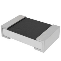
RC0805JR-0722RL
Description
RES 22 OHM 1/8W 5% 0805 SMD
Manufacturer
Yageo
Series
RC0805r
Datasheets
1.YC248-JR-07100RL.pdf
(7 pages)
2.YC358TJK-071KL.pdf
(16 pages)
3.RC0805JR-07100KL.pdf
(9 pages)
Specifications of RC0805JR-0722RL
Resistance (ohms)
22
Power (watts)
0.125W, 1/8W
Composition
Thick Film
Temperature Coefficient
±100ppm/°C
Tolerance
±5%
Size / Dimension
0.079" L x 0.049" W (2.00mm x 1.25mm)
Height
0.020" (0.50mm)
Lead Style
Surface Mount (SMD - SMT)
Package / Case
0805 (2012 Metric)
Resistance In Ohms
22.0
Case
0805 (2012 metric)
Lead Free Status / RoHS Status
Lead free / RoHS Compliant
Features
-
Other names
311-22ARTR
Available stocks
Company
Part Number
Manufacturer
Quantity
Price
Company:

Part Number:
RC0805JR-0722RL
Manufacturer:
Yageo
Quantity:
20 000
Part Number:
RC0805JR-0722RL
Manufacturer:
YAGEO/国巨
Quantity:
20 000


Mar 25, 2008 V.7
TESTS AND PROCEDURES
To guarantee zero defect production standard, Statistical Process Control is an essential part of our production
processes. Furthermore, our production process is operating in accordance with “ISO 9000” .
Essentially all tests on resistors are carried out in accordance with the schedule of “IEC publication 60115-1” in
the specified climatic category and in accordance with “IEC publication 60068” , “MIL-STD” , “JIS C 5202” , and “EIA/IS” ,
etc. In some instances deviations from the IEC recommendations are made.
Tests and their requirements are described in detail in the data sheets.
handbook, halfpage
handbook, halfpage
(10
Size 1206
Size 1206
Fig. 16 Typical temperature coefficients between the lower
Fig. 18 Typical noise level as a function of rated resistance
TC
noise
level
6
μV
V
/K)
100
200
300
300
200
100
12
measured using Quantech - equipment
and upper category temperatures
0
8
4
0
100
1
Chip Resistor Surface Mount
10
1k
100
1k
spec. level
spec. level
10 k
spec. level
10 k
100 k
100 k
1M
R (Ω)
MGA210
MGA213
R (Ω)
10 M
1M
Thick film technology
handbook, halfpage
handbook, halfpage
Size 1206
Size 1206
Fig. 17 Typical percentage change in resistance after soldering
Fig. 19 Typical percentage change in resistance after 56 days
(%)
Δ
R
(%)
R
Δ
R
R
1.2
0.8
0.4
0.4
0.8
1.2
at 40 °C and 90 to 95% relative humidity loaded with
P
0
for 10 seconds at 270 °C, completely immersed
0
2
1
1
2
nom
INTRODUCTION
1
1
10
10
100
100
1k
1k
spec. level
spec. level
spec. level
spec. level
10 k
10 k
100 k
100 k
Product specification
1M
1M
MGA214
MGA216
R (Ω)
R (Ω)
www.yageo.com
10 M
10 M
14
16
Related parts for RC0805JR-0722RL
Image
Part Number
Description
Manufacturer
Datasheet
Request
R

Part Number:
Description:
RES SMD 0805 150R 5% 0.125W TC100 10 Reel
Manufacturer:
Yageo
Part Number:
Description:
RES SMD 0805 180R 5% 0.125W TC100 10 Reel
Manufacturer:
Yageo
Part Number:
Description:
RES SMD 0805 680R 5% 0.125W TC100 10 Reel
Manufacturer:
Yageo
Part Number:
Description:
RES SMD 0805 100K 5% 0.125W TC100 13 Reel
Manufacturer:
Yageo
Part Number:
Description:
RES SMD 0805 2K20 5% 0.125W TC100 13 Reel
Manufacturer:
Yageo
Part Number:
Description:
RES SMD 0805 22K0 5% 0.125W TC100 13 Reel
Manufacturer:
Yageo
Part Number:
Description:
RES SMD 0805 270R 5% 0.125W TC100 13 Reel
Manufacturer:
Yageo
Part Number:
Description:
RES SMD 0805 3K30 5% 0.125W TC100 13 Reel
Manufacturer:
Yageo
Part Number:
Description:
RES SMD 0805 39K0 5% 0.125W TC100 13 Reel
Manufacturer:
Yageo
Datasheet:
Part Number:
Description:
RES SMD 0805 470R 5% 0.125W TC100 13 Reel
Manufacturer:
Yageo
Part Number:
Description:
RES SMD 0805 6K80 5% 0.125W TC100 13 Reel
Manufacturer:
Yageo
Part Number:
Description:
RES SMD 0805 20M0 5% 0.125W TC200 7 Reel
Manufacturer:
Yageo
Datasheet:

Part Number:
Description:
RES 100K OHM 1/8W 5% 0805 SMD
Manufacturer:
Yageo
Datasheet:
Part Number:
Description:
RES 1.2K OHM 1/8W 5% 0805 SMD
Manufacturer:
Yageo
Datasheet:
Part Number:
Description:
RES 5.1M OHM 1/8W 5% 0805 SMD
Manufacturer:
Yageo
Datasheet: