CRCW12061K00FKTA Vishay, CRCW12061K00FKTA Datasheet - Page 2
CRCW12061K00FKTA
Manufacturer Part Number
CRCW12061K00FKTA
Description
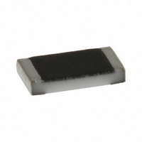
RES 1.00K OHM 1/4W 1% 1206 SMD
Manufacturer
Vishay
Series
CRCWr
Type
Thick Filmr
Specifications of CRCW12061K00FKTA
Resistance
1kohm
Temperature Coefficient
±100ppm/°C
Resistance (ohms)
1K
Power (watts)
0.25W, 1/4W
Composition
Thick Film
Tolerance
±1%
Size / Dimension
0.126" L x 0.063" W (3.20mm x 1.60mm)
Height
0.022" (0.55mm)
Lead Style
Surface Mount (SMD - SMT)
Package / Case
1206 (3216 Metric)
Resistance In Ohms
1.00K
Case
1206 (3216 metric)
Power Rating(s)
1/4W
Tolerance (+ Or -)
1%
Mounting Style
Surface Mount
Operating Temp Range
-55C to 155C
Case Style
Molded
Military Standard
Not Required
Failure Rate
Not Required
Product Length (mm)
3.2mm
Product Depth (mm)
1.6mm
Product Height (mm)
0.55mm
Resistance Tolerance
± 1%
Power Rating
250mW
Voltage Rating
200V
Resistor Element Material
Thick Film
Peak Reflow Compatible (260 C)
No
Reel Quantity
5000
Termination Type
SMD
Leaded Process Compatible
No
Mounting Type
Surface Mount
Rohs Compliant
No
Construction
Rectangular
Lead Free Status / RoHS Status
Contains lead / RoHS non-compliant
Features
-
Lead Free Status / Rohs Status
Not Compliant
Other names
CRCW1206 100 1K 1% RT1
CRCW12061001FRT1
CRCW12061001FRT1
Available stocks
Company
Part Number
Manufacturer
Quantity
Price
Company:

Part Number:
CRCW12061K00FKTA
Manufacturer:
VISHAY
Quantity:
400 000


D/CRCW e3
Vishay
Note
(1)
www.vishay.com
126
THE PRODUCT DESCRIBED HEREIN AND THIS DATASHEET ARE SUBJECT TO SPECIFIC DISCLAIMERS, SET FORTH AT
TECHNICAL SPECIFICATIONS
PARAMETER
Rated dissipation P
Limiting element voltage
U
Insulation voltage
U
Insulation resistance
Category temperature
range
Failure rate
Weight
PART NUMBER AND PRODUCT DESCRIPTION
Part Number: CRCW0603562RFKEC
Product Description: D11/CRCW0603 100 562R 1 % ET6 e3
The power dissipation on the resistor generates a temperature rise against the local ambient, depending on the heat flow support of the
printed-circuit board (thermal resistance). The rated dissipation applies only if the permitted film temperature of 155 °C is not exceeded.
D11/CRCW0603
D10/CRCW0402
D11/CRCW0603
D12/CRCW0805
D25/CRCW1206
max.
ins
CRCW0402
CRCW0603
CRCW0805
CRCW1206
CRCW1210
CRCW1218
CRCW2010
CRCW2512
CRCW1210
CRCW1218
CRCW2010
CRCW2512
(1 min)
MODEL
MODEL
AC/DC
C
R
70
C
(1)
0000 = Jumper
K = Thousand
± 200 ppm/K
± 100 ppm/K
R = Decimal
UNIT
M = Million
mg
W
h
°C
W
V
V
VALUE
-1
TCR
100
CRCW0402
0
0.063
D10/
> 75
0.65
50
For technical questions, contact:
6
Standard Thick Film Chip Resistors
RESISTANCE VALUE
This datasheet is subject to change without notice.
CRCW0603
0
562R = 562
0R0 = Jumper
TOLERANCE
> 100
10K = 10 k
1M0 = 1 M
D11/
F = ± 1.0 %
10R = 10
J = ± 5.0 %
Z = Jumper
0.1
75
2
562R
3
CRCW0805
0.125
> 200
5
D12/
150
5.5
6
K = ± 100 ppm/K
N = ± 200 ppm/K
thickfilmchip@vishay.com
CRCW1206 CRCW1210 CRCW1218 CRCW2010 CRCW2512
TOLERANCE
0 = Jumper
> 300
D25/
2
0.25
± 5 %
± 1 %
200
TCR
10
1 %
- 55 to + 155
< 0.1 x 10
> 10
R
9
> 300
- 9
200
F
0.5
16
PACKAGING
PACKAGING
K
ET1, ET5,
ET6, ET7,
EF4, E02,
E67, E82,
EA, EB,
EG, EH,
EC, ED,
EE, EF,
ET6
ET9
EK
> 300
29.5
200
1.0
E
C
Document Number: 20035
www.vishay.com/doc?91000
> 300
0.75
25.5
400
LEAD (Pb)-FREE
termination finish
Revision: 08-Mar-11
Up to 2 digits
e3 = Pure tin
SPECIAL
e3
> 300
40.5
500
1.0
Related parts for CRCW12061K00FKTA
Image
Part Number
Description
Manufacturer
Datasheet
Request
R

Part Number:
Description:
357-036-542-201 CARDEDGE 36POS DL .156 BLK LOPRO
Manufacturer:
Vishay
Datasheet:
Part Number:
Description:
357-036-542-201 CARDEDGE 36POS DL .156 BLK LOPRO
Manufacturer:
Vishay
Datasheet:
Part Number:
Description:
357-036-542-201 CARDEDGE 36POS DL .156 BLK LOPRO
Manufacturer:
Vishay
Datasheet:
Part Number:
Description:
357-036-542-201 CARDEDGE 36POS DL .156 BLK LOPRO
Manufacturer:
Vishay
Datasheet:
Part Number:
Description:
357-036-542-201 CARDEDGE 36POS DL .156 BLK LOPRO
Manufacturer:
Vishay
Datasheet:
Part Number:
Description:
357-036-542-201 CARDEDGE 36POS DL .156 BLK LOPRO
Manufacturer:
Vishay
Datasheet:
Part Number:
Description:
357-036-542-201 CARDEDGE 36POS DL .156 BLK LOPRO
Manufacturer:
Vishay
Datasheet:
Part Number:
Description:
357-036-542-201 CARDEDGE 36POS DL .156 BLK LOPRO
Manufacturer:
Vishay
Datasheet:
Part Number:
Description:
357-036-542-201 CARDEDGE 36POS DL .156 BLK LOPRO
Manufacturer:
Vishay
Datasheet:
Part Number:
Description:
357-036-542-201 CARDEDGE 36POS DL .156 BLK LOPRO
Manufacturer:
Vishay
Datasheet:
Part Number:
Description:
357-036-542-201 CARDEDGE 36POS DL .156 BLK LOPRO
Manufacturer:
Vishay
Datasheet:
Part Number:
Description:
357-036-542-201 CARDEDGE 36POS DL .156 BLK LOPRO
Manufacturer:
Vishay
Datasheet:
Part Number:
Description:
357-036-542-201 CARDEDGE 36POS DL .156 BLK LOPRO
Manufacturer:
Vishay
Datasheet:
Part Number:
Description:
357-036-542-201 CARDEDGE 36POS DL .156 BLK LOPRO
Manufacturer:
Vishay
Datasheet:
Part Number:
Description:
357-036-542-201 CARDEDGE 36POS DL .156 BLK LOPRO
Manufacturer:
Vishay
Datasheet: