V250LA40CP Littelfuse Inc, V250LA40CP Datasheet - Page 8
V250LA40CP
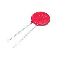
Manufacturer Part Number
V250LA40CP
Description
VARISTOR 250V C-III 20MM RADIAL
Manufacturer
Littelfuse Inc
Series
C-IIIr
Specifications of V250LA40CP
Package / Case
Disc 20mm
Number Of Circuits
1
Energy
300J
Current-surge
7kA
Maximum Ac Volts
250Vrms
Varistor Voltage
354V
Suppressor Type
Transient Voltage
Peak Surge Current @ 8/20µs
9000A
Varistor Case
20mm DISC
Clamping Voltage Vc Max
650V
Voltage Rating Vac
250V
Operating Temperature Range
-55°C To +85°C
Product
MOV
Voltage Rating Dc
250 V
Voltage Rating Ac
250 V
Clamping Voltage
650 V
Peak Surge Current
9 KA
Mounting
Radial
Dimensions
20 mm Dia.
Termination Style
Radial
Lead Free Status / RoHS Status
Lead free / RoHS Compliant
Maximum Dc Volts
-
Lead Free Status / Rohs Status
Lead free / RoHS Compliant


Varistor Products
High Energy Radial Lead
AC Bias Reliability
The C-III series of metal oxide varistors was designed for use on the AC
line. The varistor is connected across the AC line and is biased with a
constant amplitude sinusoidal voltage. It should be noted that the definition
of failure is a shift in the nominal varistor voltage (VN) exceeding ±10%.
Although this type of varistor is still functioning normally after this
magnitude of shift, devices at the lower extremities of VN tolerance
will begin to dissipate more power.
Because of this possibility, an extensive series of statistically designed
tests were performed to determine the reliability of the C-III type of varistor
under AC bias combined with high levels of temperature stress. To date,
this test has generated over 50,000 device hours of operation at a tempera-
ture of 125
voltage, measured at 1mA, of less than 2% have been recorded (Figure 8).
Transient Surge Current/Energy
Transient Capability
The transient surge rating serves as an excellent figure of merit for the C-III
varistor. This inherent surge handling capability is one of the C-III varistor’s
best features. The enhanced surge absorption capability results from
improved process uniformity and enhanced construction. The homogeneity
of the raw material powder and improved control over the sintering and
assembly processes are contributing factors to this improvement.
In the low power AC mains environment, industry standards (UL, IEC,
NEMA and IEEE) all suggest that the worst case surge occurrence will be
3kA. Such a transient event may occur up to five times over the equipment
life time (approximately 10 years). While the occu rences of five 3kA
transients is the required capability, the rated, repetitive surge current for
the C-III series is 80 pulses for the 20mm units and 40 pulses for the
VARISTOR
Ordering Information
C-III series Varistors are shipped standard in bulk pack with straight
leads and lead spacing outlined in the package dimensions on page 4-
13. Contact your Littelfuse sales representative to discuss the non-stan-
dard options outlined below.
For Lead-free and RoHS compliant parts add the letter ‘P’ after the base
part number and before any option as shown in the ordering example
below.
ex: V150LS20CP
RoHS
V300LS40CPX745
V
M(AC)
130V to 1,000V
o
Base Part #
C, although only rated at 85
Pb
SERIES DESIGNATOR/
LEAD STYLE DESIGNATOR
LC = Crimped and Clipped
LS = Straight
LT = Crimped
LU = Under Crimped
V XXX LA XX C
C-III Varistor Series
P + Optional Suffix
o
C. Changes in the nominal varistor
RELATIVE ENERGY INDICATOR
(One or Two Digits)
P: LEAD-FREE AND
RoHS COMPLIANT OPTION
Other Options
w w w . l i t t e l f u s e . c o m
Additionally, all 20mm C-III devices are listed to the “Permanently
Connected” category (10kA) of UL1449, by Underwriter’s Laboratories, Inc.
As a measure of the inherent device capability, samples of the 20mm
V130LA20C devices were subjected to a worst case repetitive transient
surges test. After 100 pulses, each of 3kA, there was negligible change
in the device characteristics. Changes in the clamping voltage, measured
at 100 amps, of less than 3% were recorded (Figure 9). Samples of the
14mm Series V175LA20C were subjected to repetitive surge occurrences
of 750A. Again, there was negligible changes in any of the device
characteristics after 2000 pulses (Figure 10). In both cases the inherent
device capability is far in excess of the expected worst case scenario.
FIGURE 10. TYPICAL REPETITIVE SURGE CURRENT
FIGURE 8. HIGH TEMPERATURE OPERATING LIFE 125
300
250
200
150
100
FIGURE 9. TYPICAL REPETITIVE SURGE CURRENT
600
550
500
450
400
350
300
500
450
400
350
300
0
0
0
(RATED FOR 1600 PULSES)
(RATED FOR 80 PULSES)
100 200 300 400 500 600 700 800 900 1000 1100
10
200
FOR 1000 HOURS AT RATED BIAS
CAPABILITY OF C-III SERIES MOVs
CAPABILITY OF C-III SERIES MOVs
20
400
30
600
40
NUMBER OF SURGES
NUMBER OF SURGES
TIME (HOURS)
50
800
60
1000
70
80
1200 1400
90 100 110 120
750A (8/20µs)
V175LA20C
V130LA20C
V130LA20C
3kA (8/20µs)
1600
o
C
55
2000
2
Related parts for V250LA40CP
Image
Part Number
Description
Manufacturer
Datasheet
Request
R

Part Number:
Description:
VARISTOR 250V 21J 7MM RADIAL LA
Manufacturer:
Littelfuse Inc
Datasheet:

Part Number:
Description:
Power Vector Modular Input Amplifiers
Manufacturer:
BOGEN COMMUNICATIONS
Datasheet:

Part Number:
Description:
FUSEHOLDER 20A MINI INLINE CRIMP
Manufacturer:
Littelfuse Inc
Datasheet:

Part Number:
Description:
FUSEHOLDER BODY ATO INLINE PNLMT
Manufacturer:
Littelfuse Inc
Datasheet:

Part Number:
Description:
FUSE 2A 63V FAST 1206
Manufacturer:
Littelfuse Inc
Datasheet:
Part Number:
Description:
FUSE 1.25A 63V FAST 1206
Manufacturer:
Littelfuse Inc
Datasheet:
Part Number:
Description:
FUSE .250A 125V FAST 1206
Manufacturer:
Littelfuse Inc
Datasheet:
Part Number:
Description:
FUSE 4A 32V FAST 1206
Manufacturer:
Littelfuse Inc
Datasheet:
Part Number:
Description:
FUSE 1.75A 63V FAST 1206
Manufacturer:
Littelfuse Inc
Datasheet:

Part Number:
Description:
FUSE 1A 32V FST 0603 LEADFREE TR
Manufacturer:
Littelfuse Inc
Datasheet:

Part Number:
Description:
FUSE 1A 32V FAST SLIM 0402
Manufacturer:
Littelfuse Inc
Datasheet:

Part Number:
Description:
FUSE 2A 125V FAST NANO2 SMD
Manufacturer:
Littelfuse Inc
Datasheet:

Part Number:
Description:
FUSE .250A 125V FAST NANO2 SMD
Manufacturer:
Littelfuse Inc
Datasheet:

Part Number:
Description:
FUSE .500A 125V FAST NANO2 SMD
Manufacturer:
Littelfuse Inc
Datasheet:

Part Number:
Description:
FUSE 1.5A 125V FAST NANO2 SMD
Manufacturer:
Littelfuse Inc
Datasheet: