V18ZA2P Littelfuse Inc, V18ZA2P Datasheet - Page 2
V18ZA2P
Manufacturer Part Number
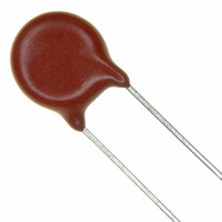
V18ZA2P
Description
VARISTOR 18V 1.5J 10MM RADIAL ZA
Manufacturer
Littelfuse Inc
Series
ZAr
Type
MOVr
Specifications of V18ZA2P
Varistor Voltage
18V
Package / Case
Disc 10mm
Number Of Circuits
1
Energy
1.5J
Current-surge
500A
Maximum Ac Volts
10Vrms
Maximum Dc Volts
14VDC
Product
MOV
Voltage Rating Dc
14 V
Voltage Rating Ac
10 V
Clamping Voltage
36 V
Peak Surge Current
500 A
Surge Energy Rating
1.5 J
Capacitance
5000 pF
Operating Temperature Range
- 55 C to + 85 C
Mounting
Through Hole
Current Rating
5 A
Dimensions
10 mm Dia. x 5 mm H
Termination Style
Radial
Brand/series
ZA Series
Current, Peak
500 A
Electric Strength
1.50 Joules
Energy Rating
1.5 Joules
Mounting Style
PC Mount
Package
Leads
Power Rating
1.5 Joules (Max.) @ +85 °C
Resistance, Insulation
1000 Megohms
Technology
Metal Oxide
Temperature, Operating, Maximum
85 °C
Temperature, Operating, Minimum
-55 °C
Terminal Type
Radial Leaded
Voltage, Ac
10 VAC
Voltage, Clamping
36 V
Voltage, Dc
14 VDC
Voltage, Operating
14.00 VDC
Voltage, Varistor
21.6
Lead Free Status / RoHS Status
Lead free / RoHS Compliant
Lead Free Status / RoHS Status
Lead free / RoHS Compliant, Lead free / RoHS Compliant


Varistor Products
Low to Medum Voltage, Radial Lead
ZA Varistor Series
Absolute Maximum Ratings
Continuous:
Transient:
Operating Ambient Temperature Range (T A ) . . . . . . . . . . . . . . . . . . . . . . . . . . . . . . . . . . . . . . . . . . . . . . . . . . . . . . . . . . . . . . . -55 to85
Storage Temperature Range (T STG ) . . . . . . . . . . . . . . . . . . . . . . . . . . . . . . . . . . . . . . . . . . . . . . . . . . . . . . . . . . . . . . . . . . . . . -55 to125
Temperature Coefficient (αV) of Clamping Voltage (V C ) at Specified Test Current . . . . . . . . . . . . . . . . . . . . . . . . . . . . . . . . . . . <0.01
Hi-Pot Encapsulation (Isolation Voltage Capability) . . . . . . . . . . . . . . . . . . . . . . . . . . . . . . . . . . . . . . . . . . . . . . . . . . . . . . . . . . . . 2500
Insulation Resistance . . . . . . . . . . . . . . . . . . . . . . . . . . . . . . . . . . . . . . . . . . . . . . . . . . . . . . . . . . . . . . . . . . . . . . . . . . . . . . . . . . . 1000
CAUTION: Stresses above those listed in “Absolute Maximum Ratings” may cause permanent damage to the device. This is a stress only rating and operation of the device
at these or any other conditions above those indicated in the operational sections of this specification is not implied.
Device Ratings and Specifications
Steady State Applied Voltage:
AC Voltage Range (V M(AC)RMS ) . . . . . . . . . . . . . . . . . . . . . . . . . . . . . . . . . . . . . . . . . . . . . . . . . . . . . . . . . . . . . . . . . . . . . . 4 to 460
DC Voltage Range (V M(DC) ) . . . . . . . . . . . . . . . . . . . . . . . . . . . . . . . . . . . . . . . . . . . . . . . . . . . . . . . . . . . . . . . . . . . . . . . . . 5.5 to 615
Peak Pulse Current (I TM )
For 8/20µs Current Wave (See Figure 2). . . . . . . . . . . . . . . . . . . . . . . . . . . . . . . . . . . . . . . . . . . . . . . . . . . . . . . . . . . . . . . . 50 to 6500
Single Pulse Energy Range (Note 1)
For 10/1000µs Current Wave (W TM ) . . . . . . . . . . . . . . . . . . . . . . . . . . . . . . . . . . . . . . . . . . . . . . . . . . . . . . . . . . . . . . . . . . . 0.1 to 52
(Dielectric must withstand indicated DC voltage for one minute per MIL-STD 202, Method 301)
68
V8ZA05
V8ZA1
V8ZA2
V12ZA05
V12ZA1
V12ZA2
V18ZA05
V18ZA1
V18ZA2
V18ZA3
V18ZA40
V22ZA05
V22ZA1
V22ZA2
V22ZA3
V24ZA50
V27ZA05
V27ZA1
V27ZA2
V27ZA4
V27ZA60
NUMBER
PART
DIA. (mm)
MODEL
DISC
SIZE
10
10
10
14
20
10
14
20
10
14
20
5
7
5
7
5
7
5
7
5
7
For ratings of individual members of a series, see Device Ratings and Specifications chart.
Z08
08Z1
08Z2
Z12
12Z1
12Z2
Z18
18Z1
Z22
22Z1
Z27
27Z1
27Z2
27Z4
27Z60
18Z2
18Z3
18Z40
22Z2
22Z3
24Z50
BRAND
(Note 1)
V
V
M(AC)
CONTINUOUS
RMS
(V)
10
10
10
10
10
14
14
14
14
14
17
17
17
17
17
4
4
4
6
6
6
MAXIMUM RATING (85
(Note 4)
V
V
M(DC)
(V)
5.5
5.5
5.5
14
14
14
14
14
18
18
18
18
18
22
22
22
22
22
DC
8
8
8
w w w . l i t t e l f u s e . c o m
ENERGY 10
100 (Note 2)
120 (Note 2)
80 (Note 2)
x 1000µs
W
0.14
0.17
0.25
0.1
0.4
0.8
0.6
1.2
0.8
1.5
3.5
0.2
0.9
2.5
(J)
2
4
1
5
TM
TRANSIENT
o
C)
CURRENT
8 x 20µs
PEAK
1000
2000
1000
2000
1000
2000
I
100
250
100
250
100
250
500
100
250
500
100
250
500
(A)
50
50
TM
(Note 3)
(Note 3)
(Note 3)
VARISTOR VOLT-
AGE AT 1mA DC
V
TEST CURRENT
MIN
14.4
14.4
14.4
14.4
14.4
18.7
18.7
18.7
18.7
19.2
NOM
23
23
23
23
23
6
6
6
9
9
9
(V)
SPECIFICATIONS (25
V
MAX
21.6
21.6
21.6
21.6
21.6
31.1
31.1
31.1
31.1
31.1
NOM
11
11
11
16
16
16
26
26
26
26
26
CLAMPING
(V)
MAXIMUM
VOLTAGE
V
30
22
20
37
34
30
36
36
36
36
37
43
43
43
43
43
53
53
53
53
50
8 x 20µs
C
(A)
I
2.5
2.5
2.5
2.5
2.5
10
20
10
20
10
20
PK
1
5
1
5
1
5
1
5
1
5
ZA SERIES
o
C)
TYPICAL
CAPACI-
f = 1MHz
TANCE
11000
22000
18000
13000
(pF)
1400
3000
7500
1200
2500
6000
1000
2000
5000
1600
4000
9000
1300
3000
7000
800
600
C
UNITS
%/
MΩ
o
o
V
V
A
V
J
C
C
o
C
Related parts for V18ZA2P
Image
Part Number
Description
Manufacturer
Datasheet
Request
R

Part Number:
Description:
FUSEHOLDER 20A MINI INLINE CRIMP
Manufacturer:
Littelfuse Inc
Datasheet:

Part Number:
Description:
FUSEHOLDER BODY ATO INLINE PNLMT
Manufacturer:
Littelfuse Inc
Datasheet:

Part Number:
Description:
FUSE 2A 63V FAST 1206
Manufacturer:
Littelfuse Inc
Datasheet:
Part Number:
Description:
FUSE 1.25A 63V FAST 1206
Manufacturer:
Littelfuse Inc
Datasheet:
Part Number:
Description:
FUSE .250A 125V FAST 1206
Manufacturer:
Littelfuse Inc
Datasheet:
Part Number:
Description:
FUSE 4A 32V FAST 1206
Manufacturer:
Littelfuse Inc
Datasheet:
Part Number:
Description:
FUSE 1.75A 63V FAST 1206
Manufacturer:
Littelfuse Inc
Datasheet:

Part Number:
Description:
FUSE 1A 32V FST 0603 LEADFREE TR
Manufacturer:
Littelfuse Inc
Datasheet:

Part Number:
Description:
FUSE 1A 32V FAST SLIM 0402
Manufacturer:
Littelfuse Inc
Datasheet:

Part Number:
Description:
FUSE 2A 125V FAST NANO2 SMD
Manufacturer:
Littelfuse Inc
Datasheet:

Part Number:
Description:
FUSE .250A 125V FAST NANO2 SMD
Manufacturer:
Littelfuse Inc
Datasheet:

Part Number:
Description:
FUSE .500A 125V FAST NANO2 SMD
Manufacturer:
Littelfuse Inc
Datasheet:

Part Number:
Description:
FUSE 1.5A 125V FAST NANO2 SMD
Manufacturer:
Littelfuse Inc
Datasheet:

Part Number:
Description:
FUSE 4A 125V FAST NANO2 SMD
Manufacturer:
Littelfuse Inc
Datasheet:

Part Number:
Description:
FUSE 1A 125V FAST NANO2 SMD
Manufacturer:
Littelfuse Inc
Datasheet: