ERZ-C32CK391W Panasonic - ECG, ERZ-C32CK391W Datasheet - Page 5
ERZ-C32CK391W
Manufacturer Part Number
ERZ-C32CK391W
Description
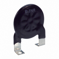
390V 32MM SURGE ABSORBER W/TAB
Manufacturer
Panasonic - ECG
Series
CKr
Datasheet
1.ERZ-C32CK201W.pdf
(5 pages)
Specifications of ERZ-C32CK391W
Varistor Voltage
390V
Current-surge
25kA
Number Of Circuits
1
Maximum Ac Volts
250VAC
Maximum Dc Volts
320VDC
Energy
350J
Package / Case
Disc 32mm with Screw Mounting
Lead Free Status / RoHS Status
Lead free / RoHS Compliant
Other names
ERZ-C32CK391B
ERZC32CK391B
ERZC32CK391W
P7161
ERZC32CK391B
ERZC32CK391W
P7161


■
Design and specifi cations are each subject to change without notice. Ask factory for the current technical specifi cations before purchase and/or use.
Should a safety concern arise regarding this product, please be sure to contact us immediately.
Standard Test Condition
Performance Characteristics (Type CK)
Varistor Voltage
Maximum Allowable
Voltage
Clamping Voltage
Rated Power
Energy
Maximum
Peak
Current
Robustness of
Terminations
(Tensile)
Vibration
Solderability
Resistance to
Soldering Heat
Dry Heat/ High
Temperature
Storage
Damp Heat/
Humidity
(Steady State)
Temperature Cycle
Dry Heat Load/
High Temperature
Load
Characteristics
2 times
1 time
Electrical characteristics shall be measured at following conditions
(Temperature: 5 to 35 °C, Humidity: Max. 85 %).
The voltage between two terminals with the specifi ed measuring
current CmA DC applied is called V
shall be made as fast as possible to avoid heat affection.
The maximum sinusoidal wave voltage (rms) or the maximum DC
voltage that can be applied continuously.
The maximum voltage between two terminals with the specifi ed
standard impulse current (8/20 µs).
The maximum power that can be applied within the specifi ed
ambient temperature.
The maximum energy within the varistor voltage change of ±10 %
when one impulse of 2 ms is applied.
The maximum current within the varistor voltage change of
±10 % with the standard impulse current (8/20 µs) applied
two times with an interval of 5 minutes.
The maximum current within the varistor voltage change of ±10 %
with the standard impulse current (8/20 µs) applied one time.
After gradually applying the force of 19.6 N (2 kgf) and keeping
the unit fi xed for ten seconds, the terminal shall be visually
examined for any damage.
After repeatedly applying a single harmonic vibration (amplitude:
0.35 mm): double amplitude: 0.7 mm with 1 minute vibration
frequency cycles (10 Hz to 55 Hz to 10 Hz) to each of three
perpendicular directions for 2 hours. Thereafter, the unit shall be
visually examined.
After dipping the terminal to a depth of approximately 3 mm from
the body in a soldering bath of 230±5 °C for 5.0±0.5 seconds,
the terminal shall be visually examined.
The terminal shall be dipped into a soldering bath having a
temperature of 350±10 °C to a point 4.0±0.8 mm from the body
of the unit and then be held there for 3.0±0.5 seconds.
change of Vc and mechanical damage shall be examined.
The specimen shall be subjected to 125±2 °C for 500 hours in a
thermostatic bath without load and then stored at room temperature
and humidity for one to two hours. Thereafter, the change of Vc
shall be measured.
The specimen shall be subjected to 40±2 °C, 90 to 95 %RH for
1000 hours without load and then stored at room temperature
and humidity for one to two hours. Thereafter, the change of Vc
shall be measured.
The temperature cycle shown below shall be repeated fi ve
times and then stored at room temperature and humidity for
one to two hours. The change of Vc and mechanical damage
shall be examined.
After being continuously applied the Maximum Allowable Voltage
at 85±2 °C for 500 hours, the specimen shall be stored at room
temperature and humidity for one to two hours. Thereafter, the
change of Vc shall be measured.
Step
1
2
3
4
Temperature (°C)
Test Methods/Description
Room Temp.
Room Temp.
–25±3
85±2
– 349 –
“ZNR” Transient/Surge Absorbers (Type CK)
C
Period (minutes)
or V
3 max.
3 max.
CmA
30
30
. The measurement
+3
+3
0
0
The
To meet the
No remarkable
damage
No remarkable
damage
Approximately 95 %
of the terminals shall
be covered with new
solder uniformly.
∆V
No remarkable
damage
∆V
∆V
No remarkable
damage
∆V
specifi ed value.
CmA
CmA
CmA
CmA
Specifi cations
/V
/V
/V
/V
———
CmA
CmA
CmA
CmA
00
< ± 5 %
< ± 5 %
< ± 5 %
< ± 10 %
Sep. 2010
Related parts for ERZ-C32CK391W
Image
Part Number
Description
Manufacturer
Datasheet
Request
R

Part Number:
Description:
Varistors 25V 10A CLAMP
Manufacturer:
Panasonic
Datasheet:

Part Number:
Description:
Varistors ERZ-V07D271
Manufacturer:
Panasonic
Datasheet:
Part Number:
Description:
Varistors 35V 5A CLAMP
Manufacturer:
Panasonic
Datasheet:
Part Number:
Description:
Varistors 250V 50A CLAMP
Manufacturer:
Panasonic
Datasheet:
Part Number:
Description:
Varistors 75V 5A CLAMP
Manufacturer:
Panasonic
Datasheet:
Part Number:
Description:
Varistors 50V 10A CLAMP
Manufacturer:
Panasonic
Datasheet:
Part Number:
Description:
Varistors 270V 25A CLAMP
Manufacturer:
Panasonic
Datasheet:
Part Number:
Description:
Varistors 200V 50A CLAMP
Manufacturer:
Panasonic
Datasheet:
Part Number:
Description:
Varistors 275V 50A CLAMP
Manufacturer:
Panasonic
Datasheet:
Part Number:
Description:
Varistors 510V 4500A ZNR SUR ABSORBER 14MM
Manufacturer:
Panasonic
Datasheet:


Part Number:
Description:
MICROPHONE OMNI 6X2.2MM W/CAP
Manufacturer:
Panasonic - ECG
Datasheet:

Part Number:
Description:
CAP .01UF 100V PEN FILM 1210 5%
Manufacturer:
Panasonic - ECG
Datasheet:

Part Number:
Description:
FILTER LINE 23.3MH 2A
Manufacturer:
Panasonic - ECG
Datasheet:

Part Number:
Description:
SAW FILTER PCS 1960 MHZ 50/150
Manufacturer:
Panasonic - ECG
Datasheet: