RL0402FR-070R18L Yageo, RL0402FR-070R18L Datasheet - Page 4
RL0402FR-070R18L
Manufacturer Part Number
RL0402FR-070R18L
Description
RES .18 OHM 1/16W 1% 0402 SMD
Manufacturer
Yageo
Series
RLr
Datasheets
1.YC248-JR-07100RL.pdf
(7 pages)
2.YC358TJK-071KL.pdf
(16 pages)
3.RL0402FR-070R56L.pdf
(9 pages)
Specifications of RL0402FR-070R18L
Temperature Coefficient
±800ppm/°C
Resistance (ohms)
0.18
Power (watts)
0.063W, 1/16W
Composition
Thick Film
Tolerance
±1%
Size / Dimension
0.039" L x 0.020" W (1.00mm x 0.50mm)
Height
0.014" (0.35mm)
Lead Style
Surface Mount (SMD - SMT)
Package / Case
0402 (1005 Metric)
Resistance In Ohms
0.18
Case
0402 (1005 metric)
Resistance
0.18ohm
Resistance Tolerance
± 1%
Power Rating
63mW
Resistor Element Material
Thick Film
Resistor Case Style
0402
Svhc
No SVHC (15-Dec-2010)
Lead Free Status / RoHS Status
Lead free / RoHS Compliant
Features
-
Lead Free Status / RoHS Status
Lead free / RoHS Compliant, Lead free / RoHS Compliant
Other names
311-.18PTR
Available stocks
Company
Part Number
Manufacturer
Quantity
Price
Company:

Part Number:
RL0402FR-070R18L
Manufacturer:
Yageo
Quantity:
8 000


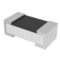
CONSTRUCTION
The resistors are constructed out of a high-grade ceramic
body. Internal metal electrodes are added at each end and
connected by a resistive paste. The composition of the
paste is adjusted to give the approximate required
resistance and laser cutting of this resistive layer that
achieves tolerance trims the value. The resistive layer is
covered with a protective coat and printed with the
resistance value. Finally, the two external terminations
(matte tin) are added. See fig. 4.
DIMENSIONS
MARKING
RL0805 / RL1206 / RL1210 /RL1218 / RL2010 / RL2512
RL0603: R≥100 m X IN E-24 SERIES, R = 10/20/30/40/50/60 mΩ
RL0402 / RL0603: R<100 m X EXCEPT 10/20/30/40/50/60 mΩ
For further marking information, please see special data sheet “Chip resistors marking”.
TYPE
RL0402
RL0603
RL0805
RL1206
RL1210
RL1218
RL2010
RL2512
Mar 22, 2010 V.5
Table 1 For outlines see fig. 4
Fig. 1
Fig. 2 Value = 22 mΩ
Fig. 3
1.00 ±0.10 0.50 ±0.05 0.35 ±0.05 0.20 ±0.10 0.25 ±0.10
1.60 ±0.10 0.80 ±0.10 0.45 ±0.10 0.25 ±0.15 0.25 ±0.15
2.00 ±0.10 1.25 ±0.10 0.50 ±0.10 0.35 ±0.20 0.35 ±0.20
3.10 ±0.10 1.60 ±0.10 0.55 ±0.10 0.45 ±0.20 0.40 ±0.20
3.10 ±0.10 2.60 ±0.15 0.55 ±0.10 0.50 ±0.20 0.50 ±0.20
3.05 ±0.15 4.60 ±0.20 0.55 ±0.10 0.45 ±0.25 0.50 ±0.25
5.00 ±0.10 2.50 ±0.15 0.55 ±0.10 0.60 ±0.20 0.50 ±0.20
6.35 ±0.10 3.20 ±0.15 0.55 ±0.10 0.60 ±0.20 0.50 ±0.20
Value = 20 mΩ
L (mm) W (mm)
020
Chip Resistor Surface Mount
YNSC005
YNSC006
ynsc007
H (mm)
E-24 series / Non-series (R= 25/40/50/60/250/400/500 mΩ): 4 digits
The “R” is used as a decimal point; the other 3 digits are significant.
3 digits
The “R” is used as a decimal point; the other 2 digits are significant.
No marking
I
1
(mm)
I
2
(mm)
RL
SERIES
O
O
U
U
For dimension see Table 1
H
W
Fig. 4 Chip resistor outlines
T
T
0402 to 2512
L
L
I
I
N
N
I 2
I
1
E
E
S
S
L
marking layer
protective coat
resistive layer
inner electrode
termination (Ni / matte tin)
ceramic substrate
Product specification
www.yageo.com
4
9
Related parts for RL0402FR-070R18L
Image
Part Number
Description
Manufacturer
Datasheet
Request
R

Part Number:
Description:
RES .22 OHM 1/16W 1% 0402 SMD
Manufacturer:
Yageo
Datasheet:
Part Number:
Description:
RES .10 OHM 1/16W 1% 0402 SMD
Manufacturer:
Yageo
Datasheet:

Part Number:
Description:
Resistor
Manufacturer:
Yageo
Datasheet:
Part Number:
Description:
Resistor
Manufacturer:
Yageo
Datasheet:
Part Number:
Description:
Resistor
Manufacturer:
Yageo
Datasheet:
Part Number:
Description:
RES .56 OHM 1/16W 1% 0402 SMD
Manufacturer:
Yageo
Datasheet:
Part Number:
Description:
RES .82 OHM 1/16W 1% 0402 SMD
Manufacturer:
Yageo
Datasheet:
Part Number:
Description:
RES .12 OHM 1/16W 1% 0402 SMD
Manufacturer:
Yageo
Datasheet:
Part Number:
Description:
RES .15 OHM 1/16W 1% 0402 SMD
Manufacturer:
Yageo
Datasheet:
Part Number:
Description:
RES .27 OHM 1/16W 1% 0402 SMD
Manufacturer:
Yageo
Datasheet:
Part Number:
Description:
RES .33 OHM 1/16W 1% 0402 SMD
Manufacturer:
Yageo
Datasheet:
Part Number:
Description:
RES .68 OHM 1/16W 1% 0402 SMD
Manufacturer:
Yageo
Datasheet:
Part Number:
Description:
RES .47 OHM 1/16W 1% 0402 SMD
Manufacturer:
Yageo
Datasheet:

Part Number:
Description:
RES .39 OHM 1/16W 1% 0402 SMD
Manufacturer:
Yageo
Datasheet: