S10K25 EPCOS Inc, S10K25 Datasheet - Page 18
S10K25
Manufacturer Part Number
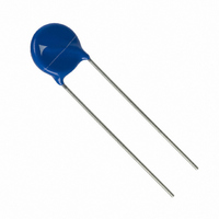
S10K25
Description
VARISTOR 25VRMS 10MM RADIAL
Manufacturer
EPCOS Inc
Series
StandarDr
Datasheet
1.S05K140.pdf
(36 pages)
Specifications of S10K25
Energy
3.7J
Varistor Voltage
39V
Current-surge
500A
Number Of Circuits
1
Maximum Ac Volts
25VAC
Maximum Dc Volts
31VDC
Package / Case
Disc 10mm
Technology
Metal Oxide
Capacitance Value
3200pF
Clamping Current
5A
Clamping Voltage
77V
Lead Style
Radial
Ac Voltage Rating (max)
25VAC
Dc Voltage Rating (max)
31VDC
Operating Temp Range
-40C to 85C
Mounting
Through Hole
Surge Current (max)
500A
Lead Spacing
5mm
Product Depth (mm)
3.8mm
Product Height (mm)
14.5mm
Product Diameter (mm)
12mm
Lead Free Status / RoHS Status
Lead free / RoHS Compliant
Other names
495-3768
B72210S250K101
S10K25
B72210S250K101
S10K25
Available stocks
Company
Part Number
Manufacturer
Quantity
Price


Reliability data
Test
Varistor voltage
Clamping voltage
Max. AC operating voltage
Surge current derating,
8/20 µs
Surge current derating,
2 ms
Electric strength
Please read Cautions and warnings and
Important notes at the end of this document.
Leaded varistors
StandarD series
Test methods/conditions
The voltage between two terminals with
the specified measuring current applied
is called V
The maximum voltage between two
terminals with the specified standard
impulse current (8/20 µs) applied.
CECC 42 000, test 4.20
1000 h at UCT
After having continuously applied
the maximum allowable voltage at UCT
±2 °C for 1000 h, the specimen shall be
stored at room temperature and normal
humidity for 1 to 2 h.
Thereafter, the change of V
measured.
CECC 42 000, test C 2.1
100 surge currents (8/20 µs), unipolar,
interval 30 s, amplitude corresponding
to derating curve for 100 impulses at
20 µs
CECC 42 000, test C 2.1
100 surge currents (2 ms), unipolar,
interval 120 s, amplitude corresponding
to derating curve for 100 impulses at
2 ms
CECC 42 000, test 4.7
Metal balls method, 2500 V
The varistor is placed in a container
holding 1.6 ±0.2 mm diameter metal
balls such that only the terminations of
the varistor are protruding.
The specified voltage shall be applied
between both terminals of the speci-
men connected together and the elec-
trode inserted between the metal balls.
v
(1 mA
DC
18
@ 0.2 … 2 s).
11/07
RMS
v
shall be
, 60 s
Requirement
To meet the specified value.
To meet the specified value.
|
|
(measured in direction
of surge current)
No visible damage
|
(measured in direction
of surge current)
No visible damage
No breakdown
∆V/V (1 mA)
∆V/V (1 mA)
∆V/V (1 mA)
|
|
|
≤10%
≤10%
≤10%
Related parts for S10K25
Image
Part Number
Description
Manufacturer
Datasheet
Request
R


Part Number:
Description:
CAP .15UF 63V METAL POLY
Manufacturer:
EPCOS Inc
Datasheet:


Part Number:
Description:
CAP .01UF 400V METAL POLY
Manufacturer:
EPCOS Inc
Datasheet:
