B72724A2170S162 EPCOS Inc, B72724A2170S162 Datasheet - Page 26
B72724A2170S162
Manufacturer Part Number
B72724A2170S162
Description
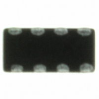
VARISTOR ARRAY 17VRMS 0612
Manufacturer
EPCOS Inc
Datasheet
1.B72762A2170S160.pdf
(34 pages)
Specifications of B72724A2170S162
Package / Case
0612 (1632 Metric)
Varistor Voltage
40V
Current-surge
30A
Number Of Circuits
4
Maximum Ac Volts
17VAC
Maximum Dc Volts
22VDC
Energy
0.075J
Voltage Rating Dc
22 V
Clamping Voltage
50 V
Surge Energy Rating
75 mJ
Capacitance
75 pF
Operating Temperature Range
- 40 C to + 85 C
Mounting
SMD/SMT
Voltage Rating Ac
17 V
Peak Surge Current
30 A
Lead Free Status / RoHS Status
Lead free / RoHS Compliant
Lead Free Status / RoHS Status
Lead free / RoHS Compliant, Lead free / RoHS Compliant
Other names
495-3428-2
CA06P4S17TLCG
CA06P4S17TLCG
Available stocks
Company
Part Number
Manufacturer
Quantity
Price

Part Number:
B72724A2170S162
Manufacturer:
EPCOS/爱普科斯
Quantity:
20 000


Note:
Leaching of the termination
Effective area at the termination might be lost if the soldering temperature and/or immersion time
are not kept within the recommended conditions. Leaching of the outer electrode should not ex-
ceed 25% of the chip end area (full length of the edge A-B-C-D) and 25% of the length A-B,
shown below as mounted on substrate.
As a single chip
7
7.1
7.2
Manual soldering with a soldering iron must be avoided, hot-air methods are recommended for
rework purposes.
7.3
All environmentally compatible agents are suitable for cleaning. Select the appropriate cleaning
solution according to the type of flux used. The temperature difference between the components
and cleaning liquid must not be greater than 100 C. Ultrasonic cleaning should be carried out
with the utmost caution. Too high ultrasonic power can impair the adhesive strength of the metal-
lized surfaces.
7.4
An excessive application of solder paste results in too high a solder fillet, thus making the chip
more susceptible to mechanical and thermal stress. Too little solder paste reduces the adhesive
strength on the outer electrodes and thus weakens the bonding to the PCB. The solder should be
applied smoothly to the end surface.
Please read Cautions and warnings and
Important notes at the end of this document.
Multilayer varistors (MLVs)
Low capacitance series
According to JEDEC J-STD-020D. Please refer to chapter 2.
Notes for proper soldering
Preheating and cooling
Repair / rework
Cleaning
Solder paste printing (reflow soldering)
Page 26 of 34
As mounted on substrate
Related parts for B72724A2170S162
Image
Part Number
Description
Manufacturer
Datasheet
Request
R


Part Number:
Description:
CAP .15UF 63V METAL POLY
Manufacturer:
EPCOS Inc
Datasheet:


Part Number:
Description:
CAP .01UF 400V METAL POLY
Manufacturer:
EPCOS Inc
Datasheet:
