RC0805FR-07115KL Yageo, RC0805FR-07115KL Datasheet - Page 12
RC0805FR-07115KL
Manufacturer Part Number
RC0805FR-07115KL
Description
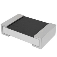
RES 115K OHM 1/8W 1% 0805 SMD
Manufacturer
Yageo
Series
RC0805r
Datasheets
1.YC248-JR-07100RL.pdf
(7 pages)
2.YC358TJK-071KL.pdf
(16 pages)
3.RC0805JR-07100KL.pdf
(9 pages)
Specifications of RC0805FR-07115KL
Resistance (ohms)
115K
Power (watts)
0.125W, 1/8W
Composition
Thick Film
Temperature Coefficient
±100ppm/°C
Tolerance
±1%
Size / Dimension
0.079" L x 0.049" W (2.00mm x 1.25mm)
Height
0.020" (0.50mm)
Lead Style
Surface Mount (SMD - SMT)
Package / Case
0805 (2012 Metric)
Resistance In Ohms
115K
Case
0805 (2012 metric)
Resistance
115 KOhms
Power Rating
0.125 Watt (1/8 Watt)
Termination Style
SMD/SMT
Voltage Rating
150 Volts
Operating Temperature Range
- 55 C to + 155 C
Dimensions
1.25 mm W x 2 mm L x 0.5 mm H
Product
Thick Film Resistors SMD
Lead Free Status / RoHS Status
Lead free / RoHS Compliant
Features
-
Lead Free Status / Rohs Status
Details
Other names
311-115KCRTR
Available stocks
Company
Part Number
Manufacturer
Quantity
Price
Company:

Part Number:
RC0805FR-07115KL
Manufacturer:
Yageo
Quantity:
8 000


Mar 25, 2008 V.7
D
D
Symbol Description
P ˆ
P ˆ
V ˆ
V ˆ
R
t
t
τ
T
T
E
i
P
E
max
i
max
nom
amb
m (max.)
F
F
I
Fig. 14 Rectangular pulses
Fig. 15 Exponential pulses
I
N
N
I
I
T
T
I
I
0.37 V max
O
O
applied peak pulse power
maximum permissible peak pulse power (Fig.12)
applied peak pulse voltage (Fig. 14)
maximum permissible peak pulse voltage (Figs. 11, 13
and 15)
nominal resistance value
pulse duration (rectangular pulses)
pulse repetition time
time constant (exponential pulses)
ambient temperature
maximum hot-spot temperature of the resistor
N
N
O
O
^
F
F
V i
V
Chip Resistor Surface Mount
^
V
S
S
Y
Y
M
M
B
B
O
O
L
L
t
τ
i
S
S
(
(
S
S
t
E
E
p
E
E
t
V max
p
^
F
F
I
I
G
G
U
U
R
R
E
E
S
S
1
1
1
1
,
YNSC059
,
MGA206
1
1
2
2
t
,
t
,
1
1
3
3
,
,
1
1
4
4
A
A
N
N
D
D
Thick film technology
1
1
5
5
)
)
E
Determine the stability of a typical resistor for
operation under the following pulse-load conditions.
C
A 100 X resistor is required to operate under the
following conditions:
Therefore:
As the operating conditions P ˆ = 1 W and
are lower than these limiting values, this resistor
may be safely used.
S
A 10 k X resistor is required to operate under the
following conditions:
Therefore:
The dashed curve of Fig. 12 shows that at t
the permissible
permissible
used.
E
X
X
INGLE PLUSE
ONTINUOUS PLUS TRAIN
V
For t
P ˆ
P ˆ
P ˆ
A
A
V ˆ = 250 V; t
max
max
i
M
i
M
=
= 10 V; t
P
P
10
100
L
L
=
i
E
= 2 W and Fig. 13 gives
E
= 10
S
2
S
10
250
=
INTRODUCTION
,
000
1
V ˆ
–5
W and
2
i
max
= 10
i
s and
=
= 10
P ˆ
max
. 6
of 400 V, so this resistor may be
–5
25
–5
= 10 W and Fig. 13 shows a
t
t
s; t
p
t
t
i
W
p
s
i
=
=
p
10
10
, 1
= 10
000
−
−
2
5
–2
=
, Fig. 12 gives
, 1
V ˆ
s
000
max
= 400 V
Product specification
www.yageo.com
V ˆ = 10 V
i
i
= 10
–5
12
16
s,
Related parts for RC0805FR-07115KL
Image
Part Number
Description
Manufacturer
Datasheet
Request
R

Part Number:
Description:
RES SMD 0805 1K20 1% 0.125W TC100 10 Reel
Manufacturer:
Yageo
Part Number:
Description:
RES SMD 0805 1K80 1% 0.125W TC100 10 Reel
Manufacturer:
Yageo
Part Number:
Description:
RES SMD 0805 33K0 1% 0.125W TC100 10 Reel
Manufacturer:
Yageo
Part Number:
Description:
RES SMD 0805 6K80 1% 0.125W TC100 10 Reel
Manufacturer:
Yageo
Part Number:
Description:
RES SMD 0805 680K 1% 0.125W TC100 10 Reel
Manufacturer:
Yageo
Part Number:
Description:
RES SMD 0805 1K00 1% 0.125W TC100 13 Reel
Manufacturer:
Yageo
Part Number:
Description:
RES SMD 0805 162R 1% 0.125W TC100 13 Reel
Manufacturer:
Yageo
Part Number:
Description:
RES SMD 0805 180K 1% 0.125W TC100 13 Reel
Manufacturer:
Yageo
Part Number:
Description:
RES SMD 0805 1M80 1% 0.125W TC100 13 Reel
Manufacturer:
Yageo
Part Number:
Description:
RES SMD 0805 2K20 1% 0.125W TC100 13 Reel
Manufacturer:
Yageo
Part Number:
Description:
RES SMD 0805 22K0 1% 0.125W TC100 13 Reel
Manufacturer:
Yageo
Part Number:
Description:
RES SMD 0805 3K30 1% 0.125W TC100 13 Reel
Manufacturer:
Yageo
Part Number:
Description:
RES SMD 0805 33K0 1% 0.125W TC100 13 Reel
Manufacturer:
Yageo
Part Number:
Description:
RES SMD 0805 4K70 1% 0.125W TC100 13 Reel
Manufacturer:
Yageo
Part Number:
Description:
RES SMD 0805 5K60 1% 0.125W TC100 13 Reel
Manufacturer:
Yageo