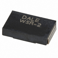
WSR2R4000FEA Vishay, WSR2R4000FEA Datasheet - Page 2

WSR2R4000FEA
Manufacturer Part Number
WSR2R4000FEA
Description
RES .40 OHM 2W 1% 4527 SMD
Manufacturer
Vishay
Series
WSRr
Specifications of WSR2R4000FEA
Temperature Coefficient
±75ppm/°C
Resistance (ohms)
0.4
Power (watts)
2W
Composition
Metal Element
Features
Current Sense
Tolerance
±1%
Size / Dimension
0.455" L x 0.275" W (11.56mm x 6.99mm)
Height
0.095" (2.41mm)
Lead Style
Surface Mount (SMD - SMT)
Package / Case
4527
Resistance In Ohms
0.40
Case
4527
Resistance
0.4ohm
Resistance Tolerance
± 1%
Power Rating
2W
Voltage Rating
0.89V
Resistor Element Material
Solid Metal Nickel-Chrome Or
Product
Metal Element Current Sensing Resistors
Operating Temperature Range
- 65 C to + 275 C
Dimensions
6.98 mm W x 11.56 mm L x 2.41 mm H
Termination Style
SMD/SMT
Lead Free Status / RoHS Status
Lead free / RoHS Compliant
Lead Free Status / RoHS Status
Lead free / RoHS Compliant, Lead free / RoHS Compliant
Other names
WSRA-.40TR
Available stocks
Company
Part Number
Manufacturer
Quantity
Price
DIMENSIONS
Note
• Embossed Carrier Tape per EIA-481-2
Document Number: 30101
Revision: 01-Jul-09
PERFORMANCE
TEST
Thermal Shock
Short Time Overload
Low Temperature Storage
High Temperature
Exposure
Bias Humidity
Mechanical Shock
Vibration
Load Life
Resistance to Solder
Heat
Moisture Resistance
PACKAGING
MODEL
WSR2 and WSR3
W
L
I
24 mm/Embossed Plastic
- 55 °C to + 150 °C, 1000 cycles, 15 min at each extreme
WSR2: 5 x rated power for 5 s
WSR3: 4 x rated power for 5 s
- 65 °C for 24 h
1000 h at + 275 °C
+ 85 °C, 85 % RH, 10 % Bias, 1000 h
100 g’s for 6 ms, 5 pulses
Frequency varied 10 Hz to 2000 Hz in 1 min, 3 directions, 12 h ± (0.5 % + 0.0005 Ω) ΔR ± (0.5 % + 0.0005 Ω) ΔR
1000 h at rated power, + 70 °C, 1.5 h “ON”, 0.5 h “OFF”
+ 260 °C Solder, 10 s to 12 s dwell, 25 mm/s emergence
MIL-STD-202 Method 106, 0 % power, 7a and 7b not required ± (0.5 % + 0.0005 Ω) ΔR ± (0.5 % + 0.0005 Ω) ΔR
T
a
Derating
TAPE WIDTH
Low Value (down to 0.001 Ω), Surface Mount
120
100
80
60
40
20
For technical questions, contact:
0
- 65
W 1
H
b
- 25
Power Metal Strip
CONDITIONS OF TEST
MODEL
MODEL
25
WSR2
WSR3
WSR2
WSR3
330 mm/13"
DIAMETER
70
75
[11.56 ± 0.813]
0.455 ± 0.032
ww2bresistors@vishay.com
L
125
®
0.155
[3.94]
SOLDER PAD DIMENSIONS in inches [millimeters]
Resistors,
a
REEL
Ambient Temperature °C
0.095 ± 0.005
[2.41 ± 0.127]
175
DIMENSIONS in inches [millimeters]
H
PIECES/REEL
± (0.5 % + 0.0005 Ω) ΔR ± (0.5 % + 0.0005 Ω) ΔR
± (0.5 % + 0.0005 Ω) ΔR ± (2.0 % + 0.0005 Ω) ΔR
± (0.5 % + 0.0005 Ω) ΔR ± (0.5 % + 0.0005 Ω) ΔR
± (1.0 % + 0.0005 Ω) ΔR ± (1.0 % + 0.0005 Ω) ΔR
± (0.5 % + 0.0005 Ω) ΔR ± (0.5 % + 0.0005 Ω) ΔR
± (0.5 % + 0.0005 Ω) ΔR ± (0.5 % + 0.0005 Ω) ΔR
± (1.0 % + 0.0005 Ω) ΔR ± (2.0 % + 0.0005 Ω) ΔR
± (0.5 % + 0.0005 Ω) ΔR ± (0.5 % + 0.0005 Ω) ΔR
225
1500
0.100 ± 0.010
[2.54 ± 0.254]
WSR2
0.230
[5.84]
275
T
b
TEST LIMITS
0.275 ± 0.005
[6.98 ± 0.127]
W
Vishay Dale
CODE
www.vishay.com
EA
WSR3
0.205
[5.21]
0.215 ± 0.005
[5.46 ± 0.127]
l
WSR
W
1
31


