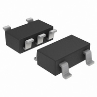
NCP360SNAIT1G ON Semiconductor, NCP360SNAIT1G Datasheet - Page 4

NCP360SNAIT1G
Manufacturer Part Number
NCP360SNAIT1G
Description
IC CTLR USB POS OVP PMOSF SOT235
Manufacturer
ON Semiconductor
Datasheet
1.NCP360SNAET1G.pdf
(13 pages)
Specifications of NCP360SNAIT1G
Voltage - Working
1.2 ~ 20V
Voltage - Clamping
7.4V
Technology
Mixed Technology
Number Of Circuits
1
Applications
USB
Package / Case
TSOT-23-5, TSOT-5, TSOP-5
Number Of Voltages Monitored
1
Monitored Voltage
1.2 V to 20 V
Manual Reset
Not Resettable
Watchdog
No Watchdog
Supply Voltage (max)
20 V
Supply Voltage (min)
1.2 V
Maximum Operating Temperature
+ 85 C
Mounting Style
SMD/SMT
Minimum Operating Temperature
- 40 C
Lead Free Status / RoHS Status
Lead free / RoHS Compliant
Power (watts)
-
Lead Free Status / Rohs Status
Lead free / RoHS Compliant
Available stocks
Company
Part Number
Manufacturer
Quantity
Price
Company:
Part Number:
NCP360SNAIT1G
Manufacturer:
ON Semiconductor
Quantity:
2 350
Part Number:
NCP360SNAIT1G
Manufacturer:
ON/安森美
Quantity:
20 000
Stresses exceeding Maximum Ratings may damage the device. Maximum Ratings are stress ratings only. Functional operation above the Recommended
Operating Conditions is not implied. Extended exposure to stresses above the Recommended Operating Conditions may affect device reliability.
1. With minimum PCB area. By decreasing R
2. R
3. Human Body Model, 100 pF discharged through a 1.5 kW resistor following specification JESD22/A114.
4. Machine Model, 200 pF discharged through all pins following specification JESD22/A115.
5. Compliant with JEDEC Latch−up Test, up to maximum voltage range.
MAXIMUM RATINGS
Minimum Voltage (IN to GND)
Minimum Voltage (All others to GND)
Maximum Voltage (IN to GND)
Maximum Voltage (All others to GND)
Maximum Current from Vin to Vout (PMOS) (Note 1)
Thermal Resistance, Junction−to−Air (Note 2)
Operating Ambient Temperature Range
Storage Temperature Range
Junction Operating Temperature
ESD Withstand Voltage (IEC 61000−4−2)
Moisture Sensitivity
Human Body Model (HBM), Model = 2 (Note 3)
Machine Model (MM) Model = B (Note 4)
qJA
is highly dependent on the PCB heat sink area (connected to PAD1, UDFN). See PCB Recommendations.
Rating
qJA
, the current capability increases. See PCB recommendation page 9.
http://onsemi.com
TSOP−5
UDFN
4
Symbol
Vmax
Vmin
Vmax
Vmin
Imax
Vesd
R
MSL
T
T
T
qJA
stg
A
J
in
in
15 Air, 8.0 Contact
−65 to +150
−40 to +85
Level 1
Value
2000
−0.3
−0.3
600
305
260
150
200
7.0
21
°C/W
Unit
mA
kV
°C
°C
°C
V
V
V
V
V
V
−


