NUP4304MR6T1G ON Semiconductor, NUP4304MR6T1G Datasheet - Page 4
NUP4304MR6T1G
Manufacturer Part Number
NUP4304MR6T1G
Description
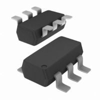
IC DIODE ARRAY LO CAP ESD SC74-6
Manufacturer
ON Semiconductor
Datasheet
1.NUP4304MR6T1G.pdf
(6 pages)
Specifications of NUP4304MR6T1G
Voltage - Breakdown
70V
Polarization
4 Channel Array - Bidirectional
Mounting Type
Surface Mount
Package / Case
SC-74-6
Applications
General Purpose
Number Of Circuits
4
Voltage - Working
70V
Technology
Diode Array
Product
Standard Recovery Rectifier
Configuration
Octal
Reverse Voltage
70 V
Forward Voltage Drop
1.25 V at 0.15 A
Forward Continuous Current
0.2 A
Max Surge Current
0.5 A
Reverse Current Ir
2.5 uA
Mounting Style
SMD/SMT
Maximum Operating Temperature
+ 85 C
Minimum Operating Temperature
- 40 C
Lead Free Status / RoHS Status
Lead free / RoHS Compliant
Power (watts)
-
Voltage - Clamping
-
Lead Free Status / Rohs Status
Lead free / RoHS Compliant
Other names
NUP4304MR6T1G
NUP4304MR6T1GOSTR
NUP4304MR6T1GOSTR
Available stocks
Company
Part Number
Manufacturer
Quantity
Price
Company:

Part Number:
NUP4304MR6T1G
Manufacturer:
ON
Quantity:
6 000
Company:
Part Number:
NUP4304MR6T1G
Manufacturer:
ON
Quantity:
30 000
Part Number:
NUP4304MR6T1G
Manufacturer:
ON/安森美
Quantity:
20 000


designed to protect sensitive electronics such as
communications systems, computers, and computer
peripherals against damage due to ESD events or transient
overvoltage conditions. Because of its low capacitance, it
can be used on high speed I/O data lines. The integrated
design of the NUP4304MR6 offers surge rated, low
capacitance steering diodes integrated in a single package
(TSOP−6). If a transient condition occurs, the steering
diodes will drive the transient to the positive rail of the
power supply or to ground.
NUP4304MR6 Configuration Options
against transient overvoltage conditions by driving them to
a fixed reference point for clamping purposes. The steering
diodes will be forward biased whenever the voltage on the
protected line exceeds the reference voltage (Vf or Vcc+Vf).
The diodes will force the transient current to bypass the
sensitive circuit.
reference is connected at pin 5. This pin must be connected
directly to ground by using a ground plane to minimize the
PCB’s ground inductance. It is very important to reduce the
PCB trace lengths as much as possible to minimize parasitic
inductance.
Option 1
positive supply rail (Vcc), the data lines are referenced to the
supply voltage. Biasing of the steering diodes reduces their
capacitance.
The NUP4304MR6 is a low capacitance diode array
The NUP4304MR6 is able to protect up to four data lines
Data lines are connected at pins 1, 3, 4 and 6. The negative
Protection of four data lines using Vcc as reference.
For this configuration, connect pin 2 directly to the
I/O 1
I/O 2
I/O 3
I/O 4
V
CC
1
2
3
6
5
4
APPLICATIONS INFORMATION
http://onsemi.com
4
Option 2
as a reference and an external TVS diode.
external TVS diode may be added across V
This will prevent overvoltage conditions on the supply rail
protecting the supply and other circuits connected to it.
Option 3
isolation resistor.
by connecting a series resistor between pin 2 and V
10 kW resistor is recommended for this application. This
will maintain bias on the internal steering diodes, reducing
their capacitance.
Protection of four data lines and the supply rail using V
If additional protection of the supply rail is desired, an
Protection of four data lines with bias and power supply
The NUP4304MR6 can be isolated from the power supply
I/O 1
I/O 2
I/O 3
I/O 4
I/O 1
I/O 2
I/O 3
I/O 4
10 k
V
V
CC
CC
1
2
3
1
2
3
6
5
4
6
5
4
CC
and ground.
CC
. A
CC
Related parts for NUP4304MR6T1G
Image
Part Number
Description
Manufacturer
Datasheet
Request
R

Part Number:
Description:
ON Semiconductor [VOLTAGE REGULATOR]
Manufacturer:
ON Semiconductor
Datasheet:
Part Number:
Description:
357-036-542-201 CARDEDGE 36POS DL .156 BLK LOPRO
Manufacturer:
ON Semiconductor
Datasheet:
Part Number:
Description:
357-036-542-201 CARDEDGE 36POS DL .156 BLK LOPRO
Manufacturer:
ON Semiconductor
Datasheet:
Part Number:
Description:
357-036-542-201 CARDEDGE 36POS DL .156 BLK LOPRO
Manufacturer:
ON Semiconductor
Datasheet:
Part Number:
Description:
357-036-542-201 CARDEDGE 36POS DL .156 BLK LOPRO
Manufacturer:
ON Semiconductor
Datasheet:
Part Number:
Description:
357-036-542-201 CARDEDGE 36POS DL .156 BLK LOPRO
Manufacturer:
ON Semiconductor
Datasheet:
Part Number:
Description:
357-036-542-201 CARDEDGE 36POS DL .156 BLK LOPRO
Manufacturer:
ON Semiconductor
Datasheet:
Part Number:
Description:
357-036-542-201 CARDEDGE 36POS DL .156 BLK LOPRO
Manufacturer:
ON Semiconductor
Datasheet:
Part Number:
Description:
357-036-542-201 CARDEDGE 36POS DL .156 BLK LOPRO
Manufacturer:
ON Semiconductor
Datasheet:
Part Number:
Description:
357-036-542-201 CARDEDGE 36POS DL .156 BLK LOPRO
Manufacturer:
ON Semiconductor
Datasheet:
Part Number:
Description:
357-036-542-201 CARDEDGE 36POS DL .156 BLK LOPRO
Manufacturer:
ON Semiconductor
Datasheet:
Part Number:
Description:
Manufacturer:
ON Semiconductor
Datasheet:
Part Number:
Description:
Manufacturer:
ON Semiconductor
Datasheet:
Part Number:
Description:
Manufacturer:
ON Semiconductor
Datasheet: