SP721APP Littelfuse Inc, SP721APP Datasheet - Page 2
SP721APP
Manufacturer Part Number
SP721APP
Description
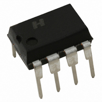
TVS ARRAY ESD 6 INPUT 8-DIP
Manufacturer
Littelfuse Inc
Series
SP721r
Type
Dioder
Specifications of SP721APP
Package / Case
8-DIP
Voltage - Working
30V
Technology
Mixed Technology
Number Of Circuits
6
Applications
General Purpose
Current Rating
+/- 5 A
Forward Voltage Drop
2 V
Operating Voltage
2 V to 30 V
Channels
6 Channels
Capacitance
3 pF
Operating Temperature Range
- 40 C to + 105 C
Brand/series
SP721 Series
Current, Surge
±3 A
Dimensions
10.16mmL×7.11mmW×4.95mmH
Mounting Type
SMD
Primary Type
Transient Voltage Surge Suppressor
Voltage, Supply
2 to 30 V
Lead Free Status / RoHS Status
Lead free / RoHS Compliant
Power (watts)
-
Voltage - Clamping
-
Lead Free Status / Rohs Status
Lead free / RoHS Compliant
Other names
F2720
Available stocks
Company
Part Number
Manufacturer
Quantity
Price

Part Number:
SP721APP
Manufacturer:
LITTELFUSE/力特
Quantity:
20 000


TVS Diode Arrays
Electronic Protection Array for ESD and Overvoltage Protection
The SP721 is an array of SCR/Diode bipolar structures for ESD and
over-voltage protection to sensitive input circuits. The SP721 has 2
protection SCR/Diode device structures per input. There are a total of
6 available inputs that can be used to protect up to 6 external signal or
bus lines. Over-voltage protection is from the IN (Pins 1 - 3 and Pins
5 - 7) to V+ or V-.
The SCR structures are designed for fast triggering at a threshold of one
+V BE diode threshold above V+ (Pin 8) or a -V BE diode threshold below
V- (Pin 4). From an IN input, a clamp to V+ is activated if a transient
pulse causes the input to be increased to a voltage level greater than
one V BE above V+. A similar clamp to V- is activated if a negative pulse,
one V BE less than V-, is applied to an IN input. Standard ESD Human
Body Model (HBM) Capability is:
Pinout
Refer to Figure 1 and Table 1 for further detail. Refer to Application
Notes AN9304 and AN9612 for additional information.
Ordering Information
RoHS
SP721APP
SP721ABG
SP721ABTG
PART NO.
IEC 61000-4-2
MIL-STD-3015.7 Direct, In-Circuit
STANDARD
8
HBM
Pb
TEMP. RANGE
-40 to 105
-40 to 105
-40 to 105
(
o
C)
GREEN
IN
IN
IN
V-
Air
Direct
Direct, Dual Pins
SP721 (PDIP, SOIC)
1
2
3
4
Tape and Reel
8 Ld PDIP
8 Ld SOIC
8 Ld SOIC
MODE
PACKAGE
TOP VIEW
SP721Lead-Free/Green
Lead-free
Green
Green
ENVIRONMENTAL
1.5kΩ
330Ω
330Ω
330Ω
INFORMATON
R
8
7
6
5
V+
IN
IN
IN
150pF
150pF
150pF
100pF
C
MARKING
721APP
721AG
721AG
ESD (V)
>15kV
>15kV
>4kV
>8kV
2000
1960
2500
Order
Min.
Features
• ESD Interface Capability for HBM Standards
• High Peak Current Capability
• Designed to Provide Over-Voltage Protection
• Fast Switching . . . . . . . . . . . . . . . . . . . . . . . . . . . . . . . . . 2ns Rise Time
• Low Input Leakages . . . . . . . . . . . . . . . . . . . . . . . . 1nA at 25
• Low Input Capacitance . . . . . . . . . . . . . . . . . . . . . . . . . . . . . 3pF Typical
• An Array of 6 SCR/Diode Pairs
• Operating Temperature Range . . . . . . . . . . . . . . . . . . . . -40
Applications
• Microprocessor/Logic Input Protection
• Data Bus Protection
• Analog Device Input Protection
• Voltage Clamp
Functional Block Diagram
- MIL STD 3015.7 . . . . . . . . . . . . . . . . . . . . . . . . . . . . . . . . . . . . 15kV
- IEC 61000-4-2, Direct Discharge,
- Single Input. . . . . . . . . . . . . . . . . . . . . . . . . . . . . . . . . . 4kV (Level 2)
- Two Inputs in Parallel . . . . . . . . . . . . . . . . . . . . . . . . . . 8kV (Level 4)
- IEC 61000-4-2, Air Discharge . . . . . . . . . . . . . . . . . . 15kV (Level 4)
- IEC 61000-4-5 (8/20µs). . . . . . . . . . . . . . . . . . . . . . . . . . . . . . . . ±3A
- Single Pulse, 100µs Pulse Width . . . . . . . . . . . . . . . . . . . . . . . . ±2A
- Single Pulse, 4µs Pulse Width . . . . . . . . . . . . . . . . . . . . . . . . . . ±5A
- Single-Ended Voltage Range to . . . . . . . . . . . . . . . . . . . . . . . . +30V
- Differential Voltage Range to. . . . . . . . . . . . . . . . . . . . . . . . . . . ±15V
V+
IN
V-
8
1
4
IN
2
IN
3, 5-7
o
C to 105
o
C Typical
o
C
Related parts for SP721APP
Image
Part Number
Description
Manufacturer
Datasheet
Request
R

Part Number:
Description:
IC,Overvoltage Protector,BIPOLAR,SOP,8PIN,PLASTIC
Manufacturer:
Littelfuse Inc
Datasheet:

Part Number:
Description:
FUSEHOLDER 20A MINI INLINE CRIMP
Manufacturer:
Littelfuse Inc
Datasheet:

Part Number:
Description:
FUSEHOLDER BODY ATO INLINE PNLMT
Manufacturer:
Littelfuse Inc
Datasheet:

Part Number:
Description:
FUSE 2A 63V FAST 1206
Manufacturer:
Littelfuse Inc
Datasheet:
Part Number:
Description:
FUSE 1.25A 63V FAST 1206
Manufacturer:
Littelfuse Inc
Datasheet:
Part Number:
Description:
FUSE .250A 125V FAST 1206
Manufacturer:
Littelfuse Inc
Datasheet:
Part Number:
Description:
FUSE 4A 32V FAST 1206
Manufacturer:
Littelfuse Inc
Datasheet:
Part Number:
Description:
FUSE 1.75A 63V FAST 1206
Manufacturer:
Littelfuse Inc
Datasheet:

Part Number:
Description:
FUSE 1A 32V FST 0603 LEADFREE TR
Manufacturer:
Littelfuse Inc
Datasheet:

Part Number:
Description:
FUSE 1A 32V FAST SLIM 0402
Manufacturer:
Littelfuse Inc
Datasheet:

Part Number:
Description:
FUSE 2A 125V FAST NANO2 SMD
Manufacturer:
Littelfuse Inc
Datasheet:

Part Number:
Description:
FUSE .250A 125V FAST NANO2 SMD
Manufacturer:
Littelfuse Inc
Datasheet:

Part Number:
Description:
FUSE .500A 125V FAST NANO2 SMD
Manufacturer:
Littelfuse Inc
Datasheet:

Part Number:
Description:
FUSE 1.5A 125V FAST NANO2 SMD
Manufacturer:
Littelfuse Inc
Datasheet:

Part Number:
Description:
FUSE 4A 125V FAST NANO2 SMD
Manufacturer:
Littelfuse Inc
Datasheet: