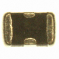
V2F114A300Y2EDP AVX Corporation, V2F114A300Y2EDP Datasheet - Page 8

V2F114A300Y2EDP
Manufacturer Part Number
V2F114A300Y2EDP
Description
VARISTOR CAP FEEDTHRU 14V 0805
Manufacturer
AVX Corporation
Series
TransFeedr
Datasheet
1.V2F105A150Y2EDP.pdf
(8 pages)
Specifications of V2F114A300Y2EDP
Package / Case
0805 (2012 Metric)
Voltage - Working
14V
Voltage - Clamping
32V
Technology
TVS with Feed Though Capacitor
Number Of Circuits
1
Applications
Telecommunications
Voltage Rating Dc
14 V
Voltage Rating Ac
10 V
Clamping Voltage
32 V
Peak Surge Current
30 Amps
Surge Energy Rating
0.1 J
Capacitance
300 pF
Current Rating
30 A
Dimensions
1.25 mm W x 2.01 mm L x 1.143 mm H
Mounting
SMD/SMT
Product
MLV
Termination Style
SMD/SMT
Tolerance
+ 100 % to - 50 %
Varistor Voltage
18.5 Volts
Lead Free Status / RoHS Status
Lead free / RoHS Compliant
Power (watts)
-
Lead Free Status / Rohs Status
Lead free / RoHS Compliant
Other names
478-2483-2
Available stocks
Company
Part Number
Manufacturer
Quantity
Price
Company:
Part Number:
V2F114A300Y2EDP
Manufacturer:
AVX/KYOCERA
Quantity:
6 000
TransFeed
AVX Multilayer Ceramic Transient Voltage Suppressors
TVS Protection and EMI Attenuation in a Single Chip
PERFORMANCE CHARACTERISTICS
SPECIFICATION COMPARISON
A comparison table showing typical element parameters and resulting
performance features for MLV and MLVF is shown above.
54
APPLICATIONS
FEATURES
Sensor/Keyboard/
Touchscreen Input
Sensor Input
Keyboard
5ph
<600nh
<0.025Ω
100pf to 2.5nf
see VI curves
>0.25 x 10
<250ps
• EMI Suppression
• Broadband I/O Filtering
• Vcc Line Conditioning
• Small Size
• Low ESR
• Ultra-fast Response Time
• Broad S21 Characteristics
MLVF
0805
12
Ω
L s
L p
R on
C
R v
R p
Typical turn on time
Typical frequency response
ANALOG
DIGITAL
DIGITAL
BOARD
BOARD
BOARD
Fig. 1 – System Interface
PARAMETER
typical
typical
typical
typical
typical
typical
By X Bus
MARKET SEGMENTS
• Computers
• Automotive
• Power Supplies
• Multimedia Add-On Cards
• Bar Code Scanners
• Remote Terminals
• Medical Instrumentation
• Test Equipment
• Transceivers
• Cellular Phones / Pagers
RF BOARD
ANALOG
N/A
<1.5nh
<0.1Ω
100pf to 5.5nf
see VI curves
>1 x 10
<500ps
DIGITAL
BOARD
BOARD
0805
MLV
12
Ω
Display
Fig. 3 – Power Conversion Circuits/Power Switching Circuits
POWER
MAIN
INPUT
TYPICAL CIRCUITS REQUIRING
TRANSIENT VOLTAGE
PROTECTION AND EMI FILTERING
The following applications and schematic diagrams
show where TransFeed TVS/ EMI filtering devices might
be used:
• System Board Level Interfaces: (Fig. 1)
• Voltage Regulation (Fig. 2)
• Power Conversion Circuits (Fig. 3)
• GaAs FET Protection (Fig. 4)
+3.3V
+5V
+12V
Digital to RF
Analog to Digital
Digital to Analog
Fig. 4 – GaAs FET Protection
Fig. 2 – Voltage Regulators
MANAGEMENT
REGULATOR
POWER
CHIP
ASIC
+3.3V
+1.8V
+
OUTPUT
INTERFACE
CARD


