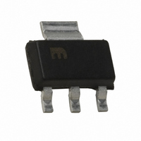
MIC5209-2.5BS Micrel Inc, MIC5209-2.5BS Datasheet - Page 10

MIC5209-2.5BS
Manufacturer Part Number
MIC5209-2.5BS
Description
IC REG LDO 500MA 2.5V LN SOT223
Manufacturer
Micrel Inc
Datasheet
1.MIC5209-3.3YS_TR.pdf
(13 pages)
Specifications of MIC5209-2.5BS
Mounting Type
Surface Mount
Regulator Topology
Positive Fixed
Voltage - Output
2.5V
Voltage - Input
Up to 16V
Voltage - Dropout (typical)
0.35V @ 500mA
Number Of Regulators
1
Current - Output
500mA
Operating Temperature
-40°C ~ 125°C
Package / Case
SOT-223 (3 leads + Tab), SC-73, TO-261
No. Of Pins
3
Voltage Regulator Type
LDO Linear
Output Current Max
500mA
Peak Reflow Compatible (260 C)
No
Current Rating
500mA
Output Voltage Max
2.5V
Leaded Process Compatible
No
Rohs Compliant
No
Lead Free Status / RoHS Status
Contains lead / RoHS non-compliant
Current - Limit (min)
-
Lead Free Status / RoHS Status
Contains lead / RoHS non-compliant, Contains lead / RoHS non-compliant
Available stocks
Company
Part Number
Manufacturer
Quantity
Price
Company:
Part Number:
MIC5209-2.5BS
Manufacturer:
MIC
Quantity:
4 245
Part Number:
MIC5209-2.5BS
Manufacturer:
MICREL/麦瑞
Quantity:
20 000
Fixed Regulator Circuits
Figure 1 shows a basic MIC5209-x.xBM (SO-8) fi xed-voltage
regulator circuit. See Figure 5 for a similar confi guration us-
ing the more thermally-effi cient MIC5209-x.xBS (SOT-223).
A 1µF minimum output capacitor is required for basic fi xed-
voltage applications.
Figure 2 includes the optional 470pF noise bypass capacitor
between BYP and GND to reduce output noise. Note that the
minimum value of C
capacitor is used.
Adjustable Regulator Circuits
The MIC5209BM/U can be adjusted to a specifi c output volt-
age by using two external resistors (Figure 3). The resistors
set the output voltage based on the equation:
This equation is correct due to the confi guration of the
bandgap reference. The bandgap voltage is relative to the
output, as seen in the block diagram. Traditional regula-
tors normally have the reference voltage relative to ground;
therefore, their equations are different from the equation for
the MIC5209BM/U.
Although ADJ is a high-impedance input, for best performance,
R2 should not exceed 470kΩ.
M9999-060906
Figure 2. Ultra-Low-Noise Fixed Voltage Regulator
Figure 3. Low-Noise Adjustable Voltage Regulator
Figure 1. Low-Noise Fixed Voltage Regulator
V
V
V
OUT
OUT
V
IN
= 1.242V
V
IN
V
IN
2
1
MIC5209-x.xBM
2
1
I I N N
E E N N
MIC5209BM
OUT
I I N N
E E N N
MIC5209-x.xBM
2
1
I I N N
EN
GND
5–8
1
must be increased when the bypass
GND
5–8
+
GND
OUT
OUT
ADJ
ADJ
OUT
OUT
BYP
BYP
R2
R1
5–8
OUT
OUT
BYP
470pF
3
4
3
4
R1
R2
3
4
1µF
V
2.2µF
OUT
V
1µF
OUT
V
OUT
10
Figure 4 includes the optional 470pF bypass capacitor from
ADJ to GND to reduce output noise.
Slot-1 Power Supply
Intel’s Pentium II processors have a requirement for a 2.5V
±5% power supply for a clock synthesizer and its associated
loads. The current requirement for the 2.5V supply is depen-
dant upon the clock synthesizer used, the number of clock
outputs, and the type of level shifter (from core logic levels to
2.5V levels). Intel estimates a worst-case load of 320mA.
The MIC5209 was designed to provide the 2.5V power
requirement for Slot-1 applications. Its guaranteed perfor-
mance of 2.5V ±3% at 500mA allows adequate margin for
all systems, and its dropout voltage of 500mV means that it
operates from a worst-case 3.3V supply where the voltage
can be as low as 3.0V.
A Slot-1 power supply (Figure 5) is easy to implement. Only
two capacitors are necessary, and their values are not criti-
cal. C
0.1µF. C
response, and compensates the internal regulator control
loop. Its value should be at least 22µF. C
be increased as much as desired.
Slot-1 Power Supply Power Dissipation
Powered from a 3.3V supply, the Slot-1 power supply of
Figure 5 has a nominal effi ciency of 75%. At the maximum
anticipated Slot 1 load (320mA), the nominal power dissipa-
tion is only 256mW.
The SOT-223 package has suffi cient thermal characteristics
for wide design margins when mounted on a single layer
copper-clad printed circuit board. The power dissipation of
the MIC5209 is calculated using the voltage drop across the
device × output current plus supply voltage × ground current.
Figure 4. Ultra-Low-Noise Adjustable Application.
IN
bypasses the internal circuitry and should be at least
OUT
V
IN
0.1µF
Figure 5. Slot-1 Power Supply
provides output fi ltering, improves transient
V
C
2
1
IN
IN
EN
IN
MIC5209BM
GND
MIC5209-x.xBS
1
5–8
I I N N
OUT
ADJ
470pF
GND
3
4
2,TAB
OUT
OUT
3
R1
R2
C
22µF
V
IN
OUT
OUT
and C
2.2µF
V
OUT
June 2006
OUT
may


