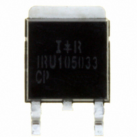
IRU1050-33CP International Rectifier, IRU1050-33CP Datasheet - Page 3

IRU1050-33CP
Manufacturer Part Number
IRU1050-33CP
Description
IC REG LDO 3.3V 5.0A 2-UTHINPAK
Manufacturer
International Rectifier
Datasheet
1.IRU1050-33CT.pdf
(8 pages)
Specifications of IRU1050-33CP
Regulator Topology
Positive Fixed
Voltage - Output
3.3V
Voltage - Input
Up to 7V
Voltage - Dropout (typical)
1.1V @ 5A
Number Of Regulators
1
Current - Output
5A
Current - Limit (min)
5.1A
Operating Temperature
0°C ~ 150°C
Mounting Type
Surface Mount
Package / Case
2-Ultra Thin-Pak
Lead Free Status / RoHS Status
Contains lead / RoHS non-compliant
Other names
*IRU1050-33CP
PIN DESCRIPTIONS
PIN # PIN SYMBOL
BLOCK DIAGRAM
APPLICATION INFORMATION
Stability
The IRU1050-33 requires the use of an output capacitor as part of the frequency compensation in order to make the
regulator stable. Typical designs for microprocessor applications use standard electrolytic capacitors with a typical
ESR in the range of 50 to 100mV and an output capacitance of 500 to 1000mF. Fortunately as the capacitance
increases, the ESR decreases resulting in a fixed RC time constant. The IRU1050-33 takes advantage of this
phenomena in making the overall regulator loop stable. For most applications a minimum of 100mF aluminum
electrolytic capacitor such as Sanyo MVGX series, Panasonic FA series as well as the Nichicon PL series insures
both stability and good transient response.
Rev. 1.4
08/01/02
1
2
3
V
IN
3
V
Gnd
V
OUT
IN
SHUTDOWN
IR WORLD HEADQUARTERS: 233 Kansas St., El Segundo, California 90245, USA Tel: (310) 252-7105
THERMAL
CURRENT
LIMIT
This pin must be connected to ground plane using a low inductance short connection.
The output of the regulator. A minimum of 10mF capacitor must be connected from this pin
to ground to insure stability.
The input pin of the regulator. Typically a large storage capacitor is connected from this
pin to ground to insure that the input voltage does not sag below the minimum dropout
voltage during the load transient response. This pin must always be 1.3V higher than V
in order for the device to regulate properly.
PIN DESCRIPTION
Figure 1 - Simplified block diagram of the IRU1050-33.
+
www.irf.com
Data and specifications subject to change without notice. 02/01
Visit us at www.irf.com for sales contact information
1.25V
TAC Fax: (310) 252-7903
IRU1050-33
+
2 V
1 Gnd
OUT
OUT
3


