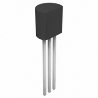
AN79L04 Panasonic - SSG, AN79L04 Datasheet - Page 10

AN79L04
Manufacturer Part Number
AN79L04
Description
VOLTAGE REG NEG 4V 100MA TO-92
Manufacturer
Panasonic - SSG
Datasheet
1.AN79L18ME1.pdf
(12 pages)
Specifications of AN79L04
Regulator Topology
Negative Fixed
Voltage - Output
-4V
Voltage - Input
Down to -35V
Number Of Regulators
1
Current - Output
100mA
Operating Temperature
0°C ~ 125°C
Mounting Type
Through Hole
Package / Case
TO-92-3 (Standard Body), TO-226
Lead Free Status / RoHS Status
Lead free / RoHS Compliant
Voltage - Dropout (typical)
-
Current - Limit (min)
-
Available stocks
Company
Part Number
Manufacturer
Quantity
Price
Company:
Part Number:
AN79L04
Manufacturer:
PANASONIC
Quantity:
5 500
AN79Lxx/AN79LxxM Series
■ Usage Notes
■ Application Circuit Example
10
1. Cautions for a basic circuit
2. Other caution items
1) Short-circuit between the input pin and GND pin
2) Floating of GND pin
off when a large capacitance capacitor has been con-
nected to the IC's load, a voltage of a capacitor con-
nected to an output pin is applied between input/out-
put of the IC and this likely results in damage of the
IC. It is necessary, therefore, to connect a diode, as
shown in figure 2, to counter the reverse bias between
input/output pins.
thermal protection circuit inside the IC does not normally operate. In this state, if the load is short-circuited or
overloaded, it is likely to damage the IC.
If the input pin is short-circuitted to GND or is cut
If a GND pin is made floating in an operating mode, an unstabilized input voltage is outputted. In this case, a
V
I
C
I
1
Figure 1
D
2
i
3
|V
Note) V
O
| = V
Never fail to adjust individually with R
−V
O
O
' 1 +
−
+
I
varies due to sample to sample variation of I
C
Input
V
O
O
2µF
Common
R
R
3
1
2
AN79Lxx
C
C
D
+ I
I
O
i
SFF00006DEB
: When a wiring from a smoothing circuit to a three-pin regulator
: Normally unnecessary. But add it in the case that there is a
2
: Deadly needed to prevent from oscillation (0.33µF to 1.0µF). It
I
Q
Bias
is long, it is likely to oscillate at output. A capacitor of 0.1µF to
0.47µF should be connected near an input pin.
is recommended to use a capacitor of a small internal imped-
ance (ex. tantalum capacitor) when using it under a low tem-
perature.
When any sudden change of load current is likely to occur, con-
nect an electrolytic capacitor of 10µF to 100µF to improve a
transitional response of output voltage.
residual voltage at the output capacitor Co even after switching
off the supply power because a current is likely to flow into an
output pin of the IC and damage the IC.
R
1
1
Output
V
O
'
R
R
2
1
−
+
−V
1µF
O
1
.
In
Bias
1
GND
Figure 2
.
2
3
Out
−
+
C
O
Output


