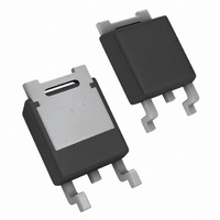
LM78M05CDTX/NOPB National Semiconductor, LM78M05CDTX/NOPB Datasheet - Page 6

LM78M05CDTX/NOPB
Manufacturer Part Number
LM78M05CDTX/NOPB
Description
IC REG 3-TERM POSITIVE TO-252
Manufacturer
National Semiconductor
Datasheet
1.LM78M05CDTNOPB.pdf
(11 pages)
Specifications of LM78M05CDTX/NOPB
Regulator Topology
Positive Fixed
Voltage - Output
5V
Voltage - Input
7.2 ~ 35 V
Number Of Regulators
1
Current - Output
500mA
Operating Temperature
-40°C ~ 125°C
Mounting Type
Surface Mount
Package / Case
TO-252-2, DPak (2 Leads + Tab), TO-252AA, SC-63
Rohs Compliant
Yes
Lead Free Status / RoHS Status
Lead free / RoHS Compliant
Voltage - Dropout (typical)
-
Current - Limit (min)
-
Other names
*LM78M05CDTX
*LM78M05CDTX/NOPB
LM78M05CDTX
*LM78M05CDTX/NOPB
LM78M05CDTX
Available stocks
Company
Part Number
Manufacturer
Quantity
Price
Part Number:
LM78M05CDTX/NOPB
Manufacturer:
NS/国半
Quantity:
20 000
www.national.com
Typical Performance Characteristics
Design Considerations
The LM78MXX/LM341XX fixed voltage regulator series has
built-in thermal overload protection which prevents the de-
vice from being damaged due to excessive junction tem-
perature.
The regulators also contain internal short-circuit protection
which limits the maximum output current, and safe-area
protection for the pass transistor which reduces the short-
circuit current as the voltage across the pass transistor is
increased.
Although the internal power dissipation is automatically lim-
ited, the maximum junction temperature of the device must
be kept below +125˚C in order to meet data sheet specifica-
tions. An adequate heatsink should be provided to assure
this limit is not exceeded under worst-case operating condi-
tions (maximum input voltage and load current) if reliable
performance is to be obtained).
1.0 HEATSINK CONSIDERATIONS
When an integrated circuit operates with appreciable cur-
rent, its junction temperature is elevated. It is important to
quantify its thermal limits in order to achieve acceptable
performance and reliability. This limit is determined by sum-
ming the individual parts consisting of a series of tempera-
ture rises from the semiconductor junction to the operating
environment. A one-dimension steady-state model of con-
Line Transient Response
Quiescent Current
01048416
01048407
6
(Continued)
duction heat transfer is demonstrated in The heat generated
at the device junction flows through the die to the die attach
pad, through the lead frame to the surrounding case mate-
rial, to the printed circuit board, and eventually to the ambi-
ent environment. Below is a list of variables that may affect
the thermal resistance and in turn the need for a heatsink.
R
Variables)
Leadframe Size & Material
No. of Conduction Pins
Die Size
Die Attach Material
Molding Compound Size
and Material
θJC
(Component
Load Transient Response
Output Impedance
R
Variables)
Mounting Pad Size,
Material, & Location
Placement of Mounting Pad
PCB Size & Material
Traces Length & Width
Adjacent Heat Sources
Volume of Air
Air Flow
Ambient Temperature
Shape of Mounting Pad
θCA
(Application
01048417
01048408


