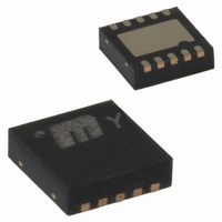
MIC2213-JSBML TR Micrel Inc, MIC2213-JSBML TR Datasheet - Page 10

MIC2213-JSBML TR
Manufacturer Part Number
MIC2213-JSBML TR
Description
IC PORTABLE PWR SEQUENCED 10-MLF
Manufacturer
Micrel Inc
Datasheet
1.MIC2213-GSBML_TR.pdf
(11 pages)
Specifications of MIC2213-JSBML TR
Regulator Topology
Positive Fixed
Voltage - Output
2.5V, 3.3V
Voltage - Input
2.25 ~ 5.5 V
Voltage - Dropout (typical)
0.12V @ 150mA, 0.24V @ 300mA
Number Of Regulators
2
Current - Output
150mA, 300mA
Current - Limit (min)
150mA, 300mA
Operating Temperature
-40°C ~ 125°C
Mounting Type
Surface Mount
Package / Case
10-MLF®, QFN
Lead Free Status / RoHS Status
Contains lead / RoHS non-compliant
Other names
MIC2213-JSBMLTR
MIC2213-JSBMLTR
MIC2213-JSBMLTR
Input Capacitor
Good bypassing is recommended from input to ground to
help improve AC performance. A 1µF capacitor or greater
located close to the IC is recommended.
Bypass Capacitor
The internal reference voltage of the MIC2213 can be by-
passed with a capacitor to ground to reduce output noise and
increase power supply rejection (PSRR). A quick-start feature
allows for quick turn-on of the output voltage regardless of
the size of the capacitor. The recommended nominal bypass
capacitor is 0.01µF, but it can be increased without limit.
Output Capacitor
Each regulator output requires a 1µF ceramic output capaci-
tor for stability. The output capacitor value can be increased
to improve transient response, but performance has been
optimized for a 1µF ceramic type output capacitor.
X7R/X5R dielectric-type ceramic capacitors are recom-
mended because of their temperature performance. X7R-type
capacitors change capacitance by 15% over their operating
temperature range and are the most stable type of ceramic
capacitors. Z5U and Y5V dielectric capacitors change value
by as much as 50% and 60% respectively over their operat-
ing temperature ranges. To use a ceramic chip capacitor with
Y5V dielectric, the value must be much higher than a X7R
ceramic capacitor to ensure the same minimum capacitance
over the equivalent operating temperature range.
M9999-101705
10
Adjustable Regulator Design
The MIC2213 allows the programming of the output voltages
1 and 2 anywhere between 1.25V and 5.5V, the maximum
operating rating of the part. Two resistors are required for each
output. Appropriate resistor values are required to prevent
the low quiescent current performance being compromised.
Resistor values recommended are between 100kΩ and
500kΩ.
The resistor values are calculated by:
where V
rately for each output.
R1 = R2
OUT
R1
R2
MIC2213 Adjustable Regulator Design
is the desired output voltage. Calculate sepa-
1.250
V
OUT
VOUT1
ADJ1
– 1
GND
VOUT2
ADJ2
October 2005
R1
R2


