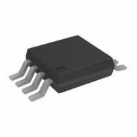
ADP3333ARM-3-REEL Analog Devices Inc, ADP3333ARM-3-REEL Datasheet - Page 7

ADP3333ARM-3-REEL
Manufacturer Part Number
ADP3333ARM-3-REEL
Description
IC REG LDO 3V 300MA 8-MSOP TR
Manufacturer
Analog Devices Inc
Series
anyCAP®r
Datasheet
1.ADP3333ARM-2.77-RL.pdf
(8 pages)
Specifications of ADP3333ARM-3-REEL
Package / Case
8-MSOP, Micro8™, 8-uMAX, 8-uSOP,
Mounting Type
Surface Mount
Current - Output
300mA
Voltage - Output
3V
Voltage - Input
Up to 12V
Operating Temperature
-25°C ~ 85°C
Regulator Topology
Positive Fixed
Voltage - Dropout (typical)
0.14V @ 300mA
Number Of Regulators
1
Current - Limit (min)
-
Calculating Junction Temperature
Device power dissipation is calculated as follows
Where I
V
Assuming the worst-case operating conditions are I
300 mA, I
device power dissipation is
The package used on the ADP3333 has a thermal resistance of
158°C/W for 4-layer boards. The junction temperature rise
above ambient will be approximately equal to
So, to limit the junction temperature to 125°C, the maximum
allowable ambient temperature is
Shutdown Mode
Applying a high signal to the shutdown pin, or connecting it to
the input pin, will turn the output ON. Pulling the shutdown
pin to 0.3 V or below, or connecting it to ground, will turn the
output OFF. In shutdown mode, the quiescent current is reduced
to less than 1 µA.
REV. A
IN
P
and V
D
=
LOAD
(
4 0
OUT
GND
.
V
P
T
and I
T
D
are the input and output voltages, respectively.
= 2.6 mA, V
J
−
A(
A
=
3 0
MAX
=
(
GND
.
V
0 308
IN
V
.
)
are load current and ground current, and
=
)
−
300
125
V
W
OUT
IN
° −
mA
C
×
= 4.0 V, and V
)
158
I
LOAD
+
48 7
(
°
4 0
C W
.
.
/
° =
+
C
V
( )
V
)
=
IN
2 0
76 3
48 7
.
OUT
I
.
mA
.
GND
°
°
C
= 3.0 V, the
C
=
LOAD
308
=
mW
–7–
Printed Circuit Board Layout Considerations
Use the following general guidelines when designing printed
circuit boards:
•
•
•
•
•
•
Keep the output capacitor as close to the output and ground
pins as possible.
Keep the input capacitor as close to the input and ground
pins as possible.
PC board traces with larger cross sectional areas will remove
more heat from the ADP3333. For optimum heat transfer,
specify thick copper and use wide traces.
Connect the NC pins (4, 5, 6, and 8) to ground for better
thermal performance.
The thermal resistance can be decreased by approximately
10% by adding a few square centimeters of copper area to
the lands connected to the pins of the LDO.
Use additional copper layers or planes to reduce the thermal
resistance. Again, connecting the other layers to the ground
and NC pins of the ADP3333 is best but not necessary.
When connecting the ground pad to other layers, use mul-
tiple vias.
ADP3333


