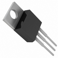
LT1086IT#PBF Linear Technology, LT1086IT#PBF Datasheet - Page 11

LT1086IT#PBF
Manufacturer Part Number
LT1086IT#PBF
Description
IC LDO REG ADJUSTABLE 1.5A TO220
Manufacturer
Linear Technology
Datasheet
1.LT1086CTPBF.pdf
(16 pages)
Specifications of LT1086IT#PBF
Regulator Topology
Positive Adjustable
Voltage - Output
1.25 ~ 23.5 V
Voltage - Input
2.55 ~ 25 V
Voltage - Dropout (typical)
1.3V @ 1.5A
Number Of Regulators
1
Current - Limit (min)
1.5A
Operating Temperature
-40°C ~ 150°C
Mounting Type
Through Hole
Package / Case
TO-220-3 (Straight Leads)
Voltage Regulator Type
Linear
Topology
LDO
Regulator Output Type
Adjustable
Polarity Type
Positive
Number Of Outputs
Single
Input Voltage (max)
25V
Package Type
TO-220
Output Current
1.5A
Power Dissipation
15W
Load Regulation
0.3%
Line Regulation
0.2%
Operating Temp Range
-40C to 150C
Operating Temperature Classification
Automotive
Dropout Voltage@current (max)
1.5@1.5A
Dropout Voltage@current (typ)
1.3@1.5A
Pin Count
3 +Tab
Mounting
Through Hole
Quiescent Current (max)
10mA
Lead Free Status / RoHS Status
Lead free / RoHS Compliant
Current - Output
-
Lead Free Status / Rohs Status
Compliant
Available stocks
Company
Part Number
Manufacturer
Quantity
Price
In both cases the junction temperature is below the
maximum rating for the respective sections, ensuring
reliable operation.
Junction-to-case thermal resistance for the K and T pack-
ages is specified from the IC junction to the bottom of the
case directly below the die. This is the lowest resistance
path for heat flow. While this is also the lowest resistance
path for the H package, most available heat sinks for this
package are of the clip-on type that attach to the cap of the
package. The data sheet specification for thermal resis-
tance for the H package is therefore written to reflect this.
APPLICATIONS
TYPICAL APPLICATIONS
U
4.25V
TO 5.25V
1N5817
INFORMATION
U
+
V
IN
10 F
TANTALUM
U
6.5V
*REQUIRED FOR STABILITY
W
+
IN
LT1086-2.85
10 F
GND
IN
U
SCSI-2 Active Termination
5V, 1.5A Regulator
OUT
LT1086
ADJ
+
TERMPWR
OUT
10 F
TANTALUM
In all cases proper mounting is required to ensure the best
possible heat flow from the die to the heat sink. Thermal
compound at the case-to-heat sink interface is strongly
recommended. In the case of the H package, mounting the
device so that heat can flow out the bottom of the case will
significantly lower thermal resistance ( a factor of 2). If
the case of the device must be electrically isolated, a
thermally conductive spacer can be used as long as its
added contribution to thermal resistance is considered.
Note that the case of all devices in this series is electrically
connected to the output.
121
1%
365
1%
0.1 F
CERAMIC
18 TOTAL
+
10 F*
TANTALUM
5V AT 1.5A
LT1086 • AI02
110
110
110
2%
2%
2%
110
110
110
LT1086 • TA03
LT1086 Series
sn1086 1086ffs
11


