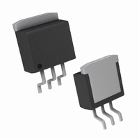
LM2937ES-3.3/NOPB National Semiconductor, LM2937ES-3.3/NOPB Datasheet - Page 3

LM2937ES-3.3/NOPB
Manufacturer Part Number
LM2937ES-3.3/NOPB
Description
IC REGULATOR LDO TO-263
Manufacturer
National Semiconductor
Datasheet
1.LM2937IMP-3.3NOPB.pdf
(11 pages)
Specifications of LM2937ES-3.3/NOPB
Regulator Topology
Positive Fixed
Voltage - Output
3.3V
Voltage - Input
Up to 26V
Voltage - Dropout (typical)
0.11V @ 50mA
Number Of Regulators
1
Current - Output
500mA
Operating Temperature
-40°C ~ 125°C
Mounting Type
Surface Mount
Package / Case
TO-263-3, D²Pak (3 leads + Tab), TO-263AA
Number Of Outputs
1
Polarity
Positive
Input Voltage Max
26 V
Output Voltage
3.3 V
Output Type
Fixed
Output Current
0.5 A
Line Regulation
9.9 mV
Load Regulation
3.3 mV
Voltage Regulation Accuracy
+/- 5 %
Maximum Operating Temperature
+ 125 C
Mounting Style
SMD/SMT
Minimum Operating Temperature
- 40 C
Lead Free Status / RoHS Status
Lead free / RoHS Compliant
Current - Limit (min)
-
Lead Free Status / Rohs Status
Details
Other names
*LM2937ES-3.3
*LM2937ES-3.3/NOPB
LM2937ES-3.3
*LM2937ES-3.3/NOPB
LM2937ES-3.3
Available stocks
Company
Part Number
Manufacturer
Quantity
Price
Part Number:
LM2937ES-3.3/NOPB
Manufacturer:
TI/德州仪器
Quantity:
20 000
Output Voltage
Line Regulation(Note 5)
Load Regulation
Quiescent Current
Output Noise
Voltage
Long Term Stability
Short-Circuit Current
Peak Line Transient
Voltage
Maximum Operational
Input Voltage
Reverse DC
Input Voltage
Reverse Transient
Input Voltage
Absolute Maximum Ratings
If Military/Aerospace specified devices are required,
please contact the National Semiconductor Sales Office/
Distributors for availability and specifications.
Electrical Characteristics
V
10 µF unless otherwise indicated. Boldface limits apply over the entire operating temperature range, of the indicated de-
vice, all other specifications are for T
Note 1: Absolute Maximum Ratings indicate limits beyond which damage to the device may occur. Electrical specifications do not apply when operating the device
outside of its rated Operating Conditions.
Note 2: The maximum allowable power dissipation at any ambient temperature is P
operation, T
125˚C and the electrical specifications do not apply. If the die temperature rises above 150˚C, the regulator will go into thermal shutdown. The junction-to-ambient
thermal resistance θ
θ
packages are used, the thermal resistance can be reduced by increasing the P.C. board copper area thermally connected to the package (see Application Hints for
more information on heatsinking).
Note 3: ESD rating is based on the human body model, 100 pF discharged through 1.5 kΩ.
Note 4: Typicals are at T
Input Voltage
Internal Power Dissipation (Note 2)
Maximum Junction Temperature
Storage Temperature Range
Lead Temperature Soldering
TO-220 (10 seconds)
TO-263 (10 seconds)
JA
IN
Continuous
Transient (t ≤ 100 ms)
is the sum of the device junction-to-case thermal resistance θ
= V
Parameter
NOM
A
is the ambient temperature, and θ
+ 5V, I
JA
Output Voltage (V
is 65˚C/W, for the TO-220 package, 73˚C/W for the TO-263 package, and 174˚C/W for the SOT-223 package. When used with a heatsink,
OUTmax
J
= 25˚C and represent the most likely parametric norm.
= 500 mA for the TO-220 and TO-263 packages, I
5 mA ≤ I
4.75V ≤ V
I
5 mA ≤ I
7V ≤ V
I
V
I
V
10 Hz–100 kHz,
I
1000 Hrs.
t
V
t
OUT
OUT
OUT
OUT
f
r
IN
IN
OUT
<
<
= (V
= 5V, I
100 ms, R
1 ms, R
= 5 mA
= 5 mA
= I
= 5 mA
≥ −0.6V, R
IN
OUT
OUTmax
A
JA
OUT
OUT
OUT
≤ 26V,
260˚C
230˚C
Conditions
= T
IN
is the junction-to-ambient thermal resistance. If this dissipation is exceeded, the die temperature will rise above
OUT
)
Internally Limited
−65˚C to +150˚C
L
≤ 26V,
(Note 4)
+ 5V),
≤ I
≤ I
J
= 100Ω
L
= 25˚C.
= I
OUTmax
OUTmax
= 100Ω
L
(Note 1)
OUTmax
= 100Ω
150˚C
JC
26V
60V
of 3˚C/W and the heatsink case-to-ambient thermal resistance. If the TO-263 or SOT-223
3
Typ
−30
−75
Operating Conditions
2.5
7.5
2.5
1.0
MAX
10
66
75
10
75
SOT-223 (Vapor Phase, 60 seconds) 215˚C
SOT-223 (Infrared, 15 seconds)
ESD Susceptibility (Note 3)
Temperature Range (Note 2)
LM2937ES, LM2937ET
LM2937IMP
Input Voltage Range
2
= (125 − T
2.5V
OUTmax
100125
Limit
2.42
2.38
2.56
2.62
A
−15
−50
0.6
25
25
10
20
60
26
)/θ
JA
, where 125 is the maximum junction temperature for
=400mA for the SOT-223 package, C
13.2
Typ
−30
−75
3.3
9.9
3.3
1.0
10
66
99
75
2
3.3V
(Note 1)
100125
Limit
3.20
3.14
3.40
3.46
−15
−50
0.6
220˚C
−40˚C ≤ T
125˚C
−40˚C ≤ T
33
33
10
20
60
26
4.75V to 26V
www.national.com
mA(Max)
A
A
mV(Max)
mV(Max)
mA(Max)
mA(Max)
V (Min)
V(Max)
V(Max)
≤
≤ 85˚C
V(Min)
A(Min)
V(Min)
V(Min)
V(Min)
V(Min)
µVrms
Units
mV
2 kV
OUT
=


