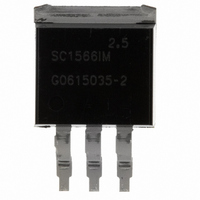
SC1566IM-2.5TRT Semtech, SC1566IM-2.5TRT Datasheet - Page 7

SC1566IM-2.5TRT
Manufacturer Part Number
SC1566IM-2.5TRT
Description
IC LDO REG 2.5V 3A TO-263-3
Manufacturer
Semtech
Datasheet
1.SC1566I5M1.8TRT.pdf
(12 pages)
Specifications of SC1566IM-2.5TRT
Regulator Topology
Positive Fixed
Voltage - Output
2.5V
Voltage - Input
Up to 5.5V
Voltage - Dropout (typical)
0.35V @ 3A
Number Of Regulators
1
Current - Output
3A
Current - Limit (min)
3A
Operating Temperature
-40°C ~ 85°C
Mounting Type
Surface Mount
Package / Case
TO-263-3, D²Pak (3 leads + Tab), TO-263AA
Lead Free Status / RoHS Status
Lead free / RoHS Compliant
Other names
SC1566IM-2.5TR
Available stocks
Company
Part Number
Manufacturer
Quantity
Price
Company:
Part Number:
SC1566IM-2.5TRT
Manufacturer:
SEMTEC
Quantity:
944
Introduction
The SC1566 is intended for applications such as
graphics cards where high current capability and very low
dropout voltage are required. It provides a very simple,
low cost solution that uses very little pcb real estate and
typically does not require a heatsink. Additional features
include an enable pin to allow for a very low power
consumption standby mode, and a fully adjustable
output (5-pin versions).
Component Selection
Input capacitor: a 4.7µF or 10µF ceramic capacitor is
recommended. This allows for the device being some
distance from any bulk capacitance on the rail.
Additionally, input droop due to load transients is reduced,
improving load transient response. Additional capacitance
may be added if required by the application.
Output capacitor: a minimum bulk capacitance of 2.2µF,
along with a 0.1µF ceramic decoupling capacitor is
recommended. Increasing the bulk capacitance will
improve the overall transient response. The use of
multiple lower value ceramic capacitors in parallel to
achieve the desired bulk capacitance will not cause
stability issues. Although designed for use with ceramic
output capacitors, the SC1566 is extremely tolerant of
output capacitor ESR values and thus will also work
comfortably with tantalum output capacitors. For refer-
ence, the phase-margin contour of Figure 1. can be used
POWER MANAGEMENT
Typical Characteristics (Cont.)
Applications Information
2005 Semtech Corp.
700
690
680
670
660
650
640
630
620
610
600
-50
VIN = 3.3V
-25
Quiescent Current vs.
Junction Temperature
0
25
T
J
50
(°C)
75
100
125
150
7
to choose an appropriate output capacitor for a given
stability requirement.
Noise immunity: in very electrically noisy environments,
it is recommended that 0.1µF ceramic capacitors be
placed from IN to GND and OUT to GND as close to the
device pins as possible.
External voltage selection resistors (5-pin parts): the
use of 1% resistors, and designing for a current flow
output (thus R2
Thermal Considerations
The power dissipation in the SC1566 is approximately
equal to the product of the output current and the input
to output voltage differential:
The absolute worst-case dissipation is given by:
For a typical scenario, V
I
V
Thus P
P
P
O
IN(MAX)
D
D
10µµA is recommended to ensure a well regulated
(
= 2.5A, therefore:
MAX
12
10
8
6
4
2
0
-50
VIN
)
= 3.465V, V
D(MAX)
VIN
VOUT
-25
Off-State Quiescent Current vs.
= 1.81W.
(
MAX
)
Junction Temperature
0
OUT(MIN)
VOUT
120k ).
I
O
25
IN
(
MIN
= 2.744V and I
= 3.3V ± 5%, V
)
T
J
50
(°C)
I
O
(
MAX
)
75
VIN
Q(MAX)
100
SC1566
www.semtech.com
(
OUT
MAX
)
= 2.8V and
VIN = 5.5V
= 1.75mA,
125
I
Q
(
MAX
)
150


