LP38501TJ-ADJ/NOPB National Semiconductor, LP38501TJ-ADJ/NOPB Datasheet - Page 12
LP38501TJ-ADJ/NOPB
Manufacturer Part Number
LP38501TJ-ADJ/NOPB
Description
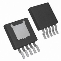
IC REG LDO 3A FLEXCAP TO263T-5
Manufacturer
National Semiconductor
Datasheet
1.LP38501TJ-ADJNOPB.pdf
(18 pages)
Specifications of LP38501TJ-ADJ/NOPB
Regulator Topology
Positive Adjustable
Voltage - Output
0.6 ~ 5 V
Voltage - Input
2.7 ~ 5.5 V
Voltage - Dropout (typical)
0.42V @ 3A
Number Of Regulators
1
Current - Output
3A
Operating Temperature
-40°C ~ 125°C
Mounting Type
Surface Mount
Package / Case
TO-263-5 Thin
For Use With
LP38501TS-ADJEV - 3A FLEXCAP LOW DROPOUT LINEAR RE
Lead Free Status / RoHS Status
Lead free / RoHS Compliant
Current - Limit (min)
-
Other names
LP38501TJ-ADJ
LP38501TJ-ADJ
LP38501TJ-ADJTR
LP38501TJ-ADJ
LP38501TJ-ADJTR


It can be seen from the figure that the output voltage starts
“correcting” back upwards after less than a micro second, and
has fully reversed direction after about 1.2 µs. This very rapid
reaction is a result of the maximum loop bandwidth (full load
is being delivered) and the feedforward effect kicking on the
drive to the FET before feedback gets fully around the loop.
In cases where extremely fast load changes occur, and output
voltage regulation better than 10% is required, the output ca-
pacitance must be increased. When selecting capacitors, it
must be understood that the better performing ones usually
cost the most. For fast changing loads, the internal parasitics
of ESR (equivalent series resistance) and ESL (equivalent
series inductance) degrade the capacitor’s ability to source
current quickly to the load. The best capacitor types for tran-
sient performance are (in order):
1.
2.
3.
4.
As a first example, larger values of ceramic capacitance will
be tried to show how much reduction can be obtained from
the 200 mV output change
only a 10 µF ceramic output capacitor. In
output capacitor is increased to 22 µF. The 200 mV transient
is reduced to about 160 mV, which is from about 11% of
V
OUT
FIGURE 6. Rising Edge, 10 µF Ceramic, 75A/µs di/dt
Multilayer Ceramic: with the lowest values of ESR and
ESL, they can have ESR values in the range of a few milli
Ohms. Disadvantage: capacitance values above about
22 µF significantly increase in cost.
Low-ESR Aluminum Electrolytics: these are aluminum
types (like OSCON) with a special electrolyte which
provides extremely low ESR values, and are the closest
to ceramic performance while still providing large
amounts of capacitance. These are cheaper (by
capacitance) than ceramic.
Solid tantalum: can provide several hundred µF of
capacitance, transient performance is slightly worse than
OSCON type capacitors, cheaper than ceramic in large
values.
General purpose aluminum electrolytics: cheap and
provide a lot of capacitance, but give the worst
performance.
down to about 9%.
(Figure
6) which was seen with
Figure
30028135
7, the 10 µF
11
In
ramic. It can be seen that the output transient is further
reduced down to about 120 mV, which is still about 6.6% of
the output voltage. This shows that a 5X increase in ceramic
capacitance from the original 10 µF only reduced the peak
voltage transient amplitude by about 40%.
In general, managing load transients is done by paralleling
ceramic capacitance with a larger bulk capacitance. In this
way, the ceramic can source current during the rapidly chang-
ing edge and the bulk capacitor can support the load current
after the first initial spike in current.
In the next test, the same 10 µF ceramic capacitor will be
paralleled with a general purpose (cheap) aluminum elec-
trolytic whose capacitance is 220 µF. As shown in
there is a small improvement over the 200 mV peak seen with
the 10 µF ceramic alone. By adding the 220 µF aluminum
capacitor, the peak is reduced to about 160 mV (the same
peak value as seen with a 22 µF ceramic capacitor alone).
Figure
FIGURE 7. 22 µF Ceramic Output Capacitor
FIGURE 8. 47 µF Ceramic Output Capacitor
8, the output capacitance is increased to 47 µF ce-
30028138
30028137
www.national.com
Figure
9,
Related parts for LP38501TJ-ADJ/NOPB
Image
Part Number
Description
Manufacturer
Datasheet
Request
R

Part Number:
Description:
Manufacturer:
National Semiconductor
Datasheet:
Part Number:
Description:
National Semiconductor [8-Bit D/A Converter]
Manufacturer:
National Semiconductor
Datasheet:
Part Number:
Description:
National Semiconductor [Media Coprocessor]
Manufacturer:
National Semiconductor
Datasheet:
Part Number:
Description:
Digitally Controlled Tone and Volume Circuit with Stereo Audio Power Amplifier, Microphone Preamp Stage and National 3D Sound
Manufacturer:
National Semiconductor
Datasheet:
Part Number:
Description:
Digitally Controlled Tone and Volume Circuit with Stereo Audio Power Amplifier, Microphone Preamp Stage and National 3D Sound
Manufacturer:
National Semiconductor
Datasheet:
Part Number:
Description:
AC97 Rev 2 Codec with Sample Rate Conversion and National 3D Sound
Manufacturer:
National Semiconductor
Part Number:
Description:
Manufacturer:
National Semiconductor
Datasheet:
Part Number:
Description:
Manufacturer:
National Semiconductor
Datasheet:
Part Number:
Description:
General Purpose, Low Voltage, Low Power, Rail-to-Rail Output Operational Amplifiers
Manufacturer:
National Semiconductor
Datasheet:
Part Number:
Description:
8-bit 20 MSPS flash A/D converter.
Manufacturer:
National Semiconductor
Datasheet:
Part Number:
Description:
Low Noise Quad Operational Amplifier
Manufacturer:
National Semiconductor
Datasheet:
Part Number:
Description:
Quad Differential Line Receivers
Manufacturer:
National Semiconductor
Datasheet:
Part Number:
Description:
Quad High Speed Trapezoidal? Bus Transceiver
Manufacturer:
National Semiconductor
Datasheet:
Part Number:
Description:
Dual Line Receiver
Manufacturer:
National Semiconductor
Datasheet: